Flexible Fixturing for Cobot Welding
Using intuitive platforms during the fixture design and implementation stages will go far in accelerating production.
Posted: January 18, 2023
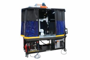
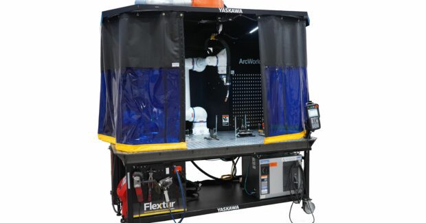
The evolution of safety standards, intelligent peripherals and ease-of-use tools for collaborative robots are boosting confidence for safe human-robot interaction. Whether coexisting in a general workspace, collaborating on the same workpiece, or synchronized to cooperate somewhere in-between, cobots with smart tools enable fast, efficient operations to tackle a variety of applications, including robotic welding for high-mix, low-volume production. For the latter application to achieve optimal results, however, repeatability is imperative.
While no solution for accuracy can be fool proof — due to variations of metals, debris and other things that can cause artifacts in process imaging — several concepts can help bridge the gap. From intuitive teaching methods with highly repeatable robots to very accurate piece parts that follow strict specifications and tolerances, multiple options exist for facilitating peak weld quality and precision.
As with any robotic process or application, users should exercise planning stages to find the most cost-effective, user-friendly solution for their specific task. Enter robotic weld fixturing, where a tool’s primary functions include:
- Providing clear access to the weld joint with the proper torch angles.
- Locating the weld joint to be within the process window. This is typically ± ¹/2 the weld wire diameter for gas metal arc welding (GMAW) and much tighter for gas tungsten arc welding (GTAW).
- Clamping and providing highly repeatable locations for the parts to provide zero gaps in the weld joint.
- Positioning the weldment in the fixture to:
- Situate the weld joints in the optimal, flat position and minimize robot motion.
- Provide the easiest load and unload orientation for the operator. Note: the preferred robotic welding position is flat or horizontal. On thin gauge material (<1/8”), vertical down should be considered based on the joint design and overall weld requirements. Also, depending on the part, breaking the weldment into sub-assemblies may be necessary.
Fixturing Concepts
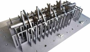
One of the leading automation efficiency factors and often overlooked, weld fixturing can range from basic clamps to more complex automated or hydraulic tooling. Automotive manufacturers and other companies that make one part thousands of times will most likely invest in a highly precise, automated tool, while smaller enterprises that can sacrifice a bit more cycle time and need more flexibility will most likely use clamping tools. Regardless of the method chosen, and for the utmost weld quality from part to part, parts should be fixtured in the same place every time.
Traditional Tooling
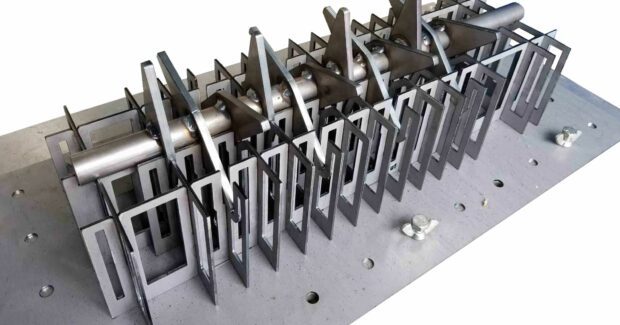
Custom designed for an individual part, traditional tooling for part holding can be made extremely precise. It can also integrate high-performance sensors to call up specific jobs or trigger alarms if wrong parts are added. Ideal for automotive manufacturers and other companies that continuously make one part, this fixturing type can be expensive and hard to justify for small- to medium-sized companies. Keep in mind, this is a permanent solution and difficult to modify. Storage space should also be a consideration when the fixture is not in use.
Flexible Tooling
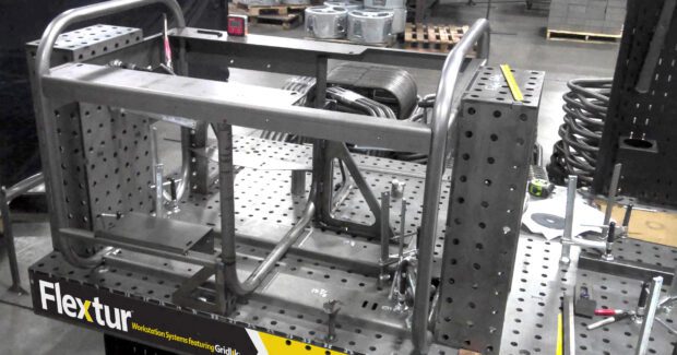
Relatively inexpensive compared to custom tooling options, a large variety of adaptive tooling can be added to collaborative welding applications. Flexible tooling platforms, such as the perforated tables offered by brands like Bluco or Flextur™, can accommodate parts of various sizes and can hold parts tight. Tolerances may have more wiggle room when compared to custom tooling. To reach the part specifications required, more clamps and brackets may be needed. Manufacturers that go this route should be mindful of the size of the table as well, making sure it is redeployable or expandable for future needs.
Fixture Design Software
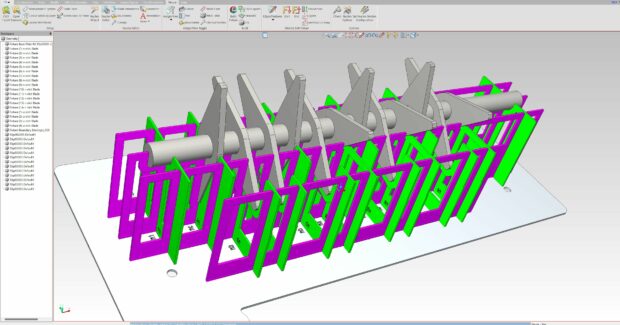
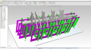
Intelligent software platforms, such as those offered by Prolim and Camtek, enable step-by-step guidance for fixture design, minimizing development time and increasing robot uptime. Powerful 3D modeling and assembly tools combine to facilitate this process. Today, users can easily match Computer Aided Design (CAD) files of parts with CAD images of fixturing components, to explore and perfect potential options. Some of these programs also enable users to cut and assemble their own tooling in-house (with proper machinery) to minimize execution time.
Poor tool design and installation has the potential to be highly inefficient and cause quality issues. Following best practices and using intuitive platforms during the fixture design and implementation stages will go far to accelerate production for a better ROI.
Subscribe to learn the latest in manufacturing.


