Updated Software Simulates and Automatically Corrects Bending Sequence
Available in two versions with varying levels of functionality, transfluid’s Windows-based t project software links geometry and material data to achieve precise bending results.
Posted: February 10, 2021
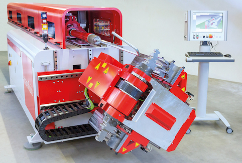
t project software from transfluid USA (Simpsonville, SC) reduces the number of steps required to manufacture a finished component. The program can be embedded in a company’s intranet to improve data security and linked to CAD, manufacturing execution system (MES) and enterprise resource planning (ERP) systems. When a bending robot is used, the software eliminates manual programming by generating all necessary movements.
Two versions are available, both as standalone or network versions:
- t project Basic converts the geometry into bending data and automatically calculates and corrects over-bending values. Geometries may be entered manually if the tubes weren’t designed in CAD.
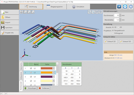
- t project Professional offers capabilities such as the multitube function, which automatically calculates and adjusts all axes to produce an alternative bending solution that avoids a collision when processing multiple tube geometries; and better display of the relative position of tubes.
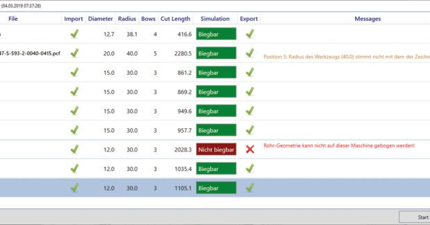
Tube geometries don’t need to be in IGES format to be imported to CAD. An import module has 30 interfaces to almost all common formats, such as IGES, STEP, JT and PCF; and an export module has 10 interfaces.


