

Robotic Welding Station Increases Strength by Ensuring Consistency
The biggest challenge to achieving a strong bond when welding thick walls are discrepancies between the CAD drawing and the in-process weld. Pemamek’s laser scan-driven control system overcomes this difficulty by automatically correcting weld path based on groove geometry.
Posted: March 19, 2020


BY MICHAEL BELL
Adaptive welding can help manufacturers of heavy-duty equipment and structures save significant time and money. A robotic cell outfitted with scanning software and controller can automatically adapt to the complex geometries often found when joining thick-walled components.
As a result, it’s no longer necessary to weld smaller pieces to make one big piece or have welders perform one task at a time. Thanks to technology, a welder can tackle multiple jobs in a fraction of the time, increasing productivity while decreasing scrap costs.
Whether the robotic welding cell uses metal inert gas (MIG), metal active gas (MAG) welding, submerged arc welding (SAW), or laser hybrid welding, the key to optimizing large-component adaptive welding is a multifeatured software control program with offline and scan-programming functions.
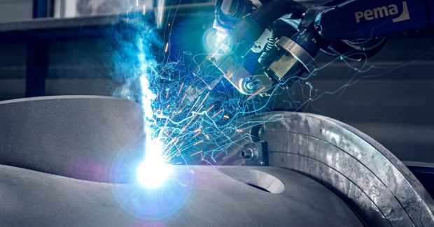
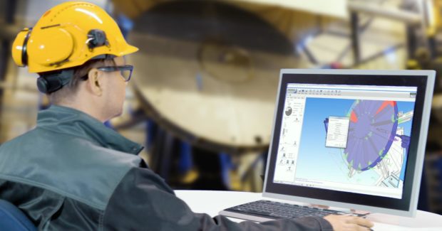
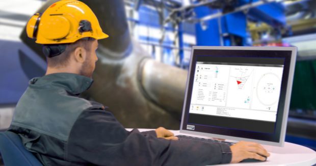
Adaptive welding is accomplished when a scan robot uses tactile and/or laser seam searching to define the grooves’ actual geometry. The scan result is imported into the software, which automatically generates a 3D image; a welding pattern is easily created using this data set. The software visualizes the scanning data for the operator, who can apply the selected pattern to the weld groove or create a new pattern that meets the required mechanical properties.
The ability to analyze bevel angle gives the operator the option to adapt welding parameters to evenly fill a groove automatically rather than manually. A control system serves as the interface for all the welding equipment, linking welding parameters, automation, and workpiece-handling equipment for seamless operation. The scan program and the control system ensure the strongest mechanical/molecular bond possible despite inconsistent groove geometry by seeing and ensuring all parts of the groove are filled.
Once a workpiece is measured and the data analyzed in the software, each welding pass is located layer by layer to the welding groove. The system automatically measures groove volume and determines the number of passes needed in each section of the weld. For thicker walls, such as those found in pressure vessels, the total number of filling passes will increase but is still controllable within the software.
A Real-World Scenario
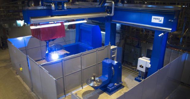
For example, we proposed a welding station consisting of one cell, one headstock positioner with hydraulic clamping system that enables PA/PB position for most of the welds, 1×16 roller bed unit with rail cars, a 3-axis robot gantry, and 2.5-meter fences and light curtains for a manufacturer of oil and gas production equipment.
Designed for centric nozzles, the system uses MAG welding for outside seams. The process is ideal for adaptive welding because of its constant wire feed, ability to be adjusted for a variety of weld parameters, and induction heating can be used for fillet welding when monitored by a control system.
All welding programs are prepared using our WeldControl 300 SCAN program, which allows three types of programming. Once parameters are entered into the system manually or via CAD file download, robotic scanning can begin. Any discrepancies between the CAD drawings and pre-weld geometries are caught and automatically corrected.
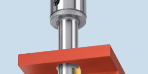
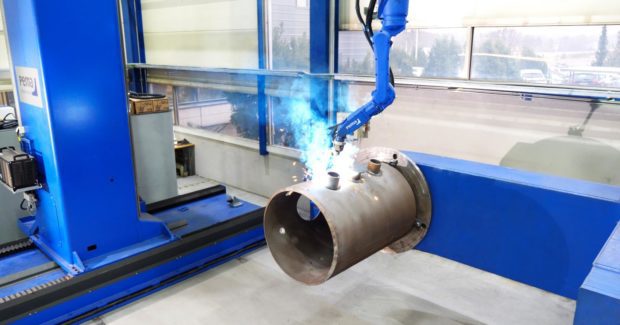
During our test run at Pemamek’s Process Center, we started by manually assembling and tack/root-welding a workpiece, lifting it to the robot cell with an overhead crane and attaching it to the positioner. The nozzle connection consisted of a 155-mm-diameter nozzle welded as a hole set-in connection to a 38-mm-thick shell.
The operator activated a scanning program on a robot teach pendant controller called CellControl 700. The scan result was imported into the WeldControl 300 Scan software and the welding pattern was created. The pattern was then transferred to the robot via the controller software.
Due to a variating bevel angle of 35 degrees to 45 degrees along the weld length, adaptive welding parameters were used to evenly fill the weld groove. Average deposition rate was 7.4 kilograms/hour, total arc-on time for the connection was 16.8 minutes, and a total of 3.3 kilograms of weld were deposited into the groove.
Other Applications
That’s just one example of how the robotic system adapts to groove variations.
Adaptive welding techniques have been used in Europe for blades in offshore towers from 230 feet to 400 feet high and more than 330 feet long. By using adaptive robotic welding techniques, joints with extremely complex geometries have been successfully welded with super strong bonds despite their size.
Subscribe to learn the latest in manufacturing.

Industry News