Selecting the Right Lead Angle and Insert for Boring Tools
The rules for twin-bore roughing and single-point fine boring are similar – but not the same. Lead angles close to 90 degrees more effectively combat potentially damaging chatter and vibration because they apply the least amount of radial pressure against the tool.
Posted: January 29, 2020
DEPTH OF CUT
There are so many factors to consider when specifying the components for a modular boring tool: boring head, tool size, number of extensions required to make it long enough, machine spindle adapter. If you think these choices are most important to boring success, though, think again. There are two more considerations: insert holder and lead angle, both of which should be selected based on application.
Conventional wisdom says to use the longest lead angle possible, thinning the chip because it allows you to increase speeds and feeds. We take a different approach. We prefer lead angles closer to 90 degrees because they apply the least amount of radial pressure against the tool. This is much more effective in combatting the chatter and vibration that compromise part productivity and tool life.
Our rough and fine boring tools and insert holders reflect this philosophy. The rules for twin-bore roughing and single-point fine boring are similar, but not the same.
Insert Holder Options for Rough Boring
Twin-cutter rough-boring tools come with a choice of two types of insert holders.
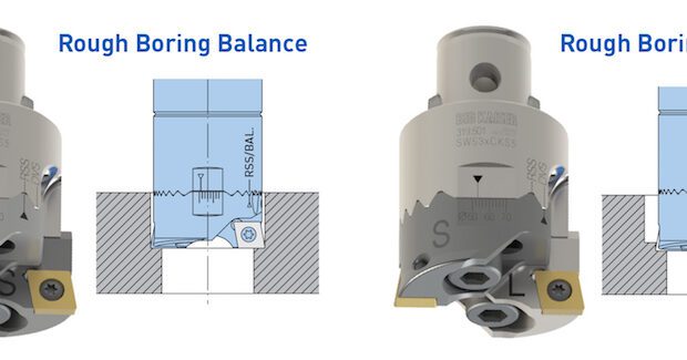
CCMT inserts with two cutting edges. Zero-degree lead or 90-degree square shoulder with a diamond-shaped insert produce a true 90-degree shoulder in a bore for a bearing or seal assembly to fit to a precise depth.
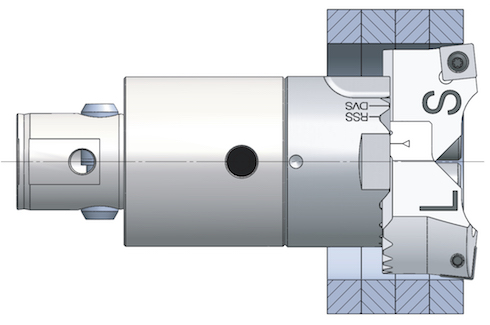
While CCMT inserts can be used for balanced cutting, the first choice for setting up a twin bore is to use stepped cutting. This provides the least amount of radial engagement, resulting in more stable cutting forces on tools with a 5:1 or greater L/D ratio (drill length to outside diameter).
Twin cutters with CCMT inserts can also be used for through-hole applications. However, when the tool is almost exiting the bore, there is likely to be a punch-out ring that can wreak havoc with the chip auger. Also, the bore will have a very rough edge and require a heavy chamfer to clean up.
This makes our second option the better choice for through-hole applications whenever possible.
SCMT inserts with four cutting edges and a 6-degree positive lead are traditionally used for balanced cutting, but tooling innovations are changing that.
In theory, a stepped cutting tool requires that the inside insert (smaller diameter) is leading the outer insert (larger diameter) by at least half of the feed per revolution. Older twin bore heads that used cam screws or height-adjusting screws couldn’t adjust enough height difference to use square inserts. Our new twin cutter heads are capable of 0.016-inch height separation, so it’s possible to use them for stepped cutting methods.
In other words, if a tool with a 0.008-inch step is fed more than 0.016 inches per revolution, the outer insert will cut at the same diameter as the inside insert. This ratio is no longer valid with a tool at 6-degree lead, and a larger step is necessary to enable each insert to bore the diameter it’s set to.
This is an instance where thin chips are a good thing. The positive lead angle reduces thrust forces upon exit, avoiding the punch-out ring and breakout where the bore ends. Stack plate weldments, where the boring tool enters and exits layers of steel plates welded together, are another example of where SCMT inserts come in handy because they don’t produce discs or rings that can get trapped between the layers and cause catastrophic tool failure.
Insert Holder Options for Fine Boring
When it comes to fine boring, lead angle generally doesn’t influence part quality. When you consider the depth of cut rarely exceeds half the insert’s radius, the angle is almost negligible to cutting forces or chip formation. Even so, there are two choices of insert holders for fine boring tools.
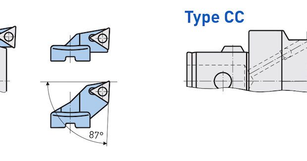
Standard triangular TCMT. In addition to three cutting edges, this insert type has far more geometries, radii, and grades than any other insert. The lead angle is 87 degrees or -3 degrees.
The common mistake is to disqualify this insert holder and choose the 90-degree type when boring to a shoulder. In reality, it should always be applied for both square-shoulder boring and through-hole operations.
A fine boring tool isn’t designed or practical for producing a square shoulder. The square shoulder feature should be left alone after the rough boring operation is completed by a twin bore or a circular milling tool.
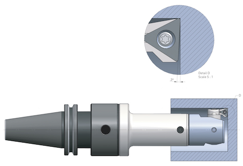
When fine boring to a square shoulder, we’ve designed the insert to have the 3-degree negative lead so it can stay off the shoulder. The tool therefore only needs to “kiss,” or blend into, the existing corner radius and we usually recommend to “stay off” the bottom by about 0.002 inch to be sure.
CCMT insert holders. The same rules of engagement apply even though it can create a true 90-degree shoulder. Only under very strict requirements of workpiece integrity, where blends aren’t allowed, such as some flight-critical aerospace parts, should the bore and shoulder be created together.
If this is the case, the programmer should back off on the feed rate about 75% when the tool is within 0.005 inch of the shoulder to minimize shoulder chatter. Also, use an insert with a pressed geometry. An up-sharp, positive insert with a 3D chip breaker can’t produce the shoulder at a consistent angle.
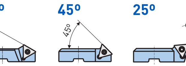
We sometimes get questions about why we offer insert holders for fine boring heads with 30-degree or 45-degree lead angle insert holders. It’s on the rare part print where a larger bore transitions to a smaller bore and the part print asks for the angle to be 30 degrees or 45 degrees with no blends.
The second reason is to produce chamfers on bores. Many customers like to have an adjustable tool to produce a wide range of bore chamfers and these insert holders provide that feature.
There are clear advantages to matching the right lead angle to the right application. When assembling a modular boring tool, don’t overlook this selection. It can be just as important to quality results, productivity, and tool life as other factors that often get much more attention.

