

Questions to Ask Before Selecting Your Next Air Gripper
Choosing the proper gripper will result in optimized performance, uptime and operator safety,
but only if all operational and design factors are adequately weighed before the decision is made.
Posted: November 22, 2019
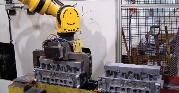


The vast array of gripper choices available for outfitting pick-and-place automation systems in the automotive, pharmaceutical, electronics and consumer-goods industries can be very confusing and overwhelming. All gripper styles have their own unique size, method of operation, operating atmospheres and required level of human interaction – which can be dazzling and daunting at first glance, but potentially lead to a hurried or uninformed selection from a sales catalog or off the shelf that doesn’t truly meet the needs of the process application. All variables must be carefully considered. Pneumatic or electric grippers can perform three basic functions:
- Part transfer to and from a conveyor, workstation or machine. Common applications are machine tending, part placement, load and unload, and boxing, crating or palletizing.
- Part orientation requires the gripper to assist in aligning a part in preparation for the next process step, such as precision orientation for applying a label, preparation for tray insertion or box packaging.
- Hold part in place requires gripping a part securely in place while an action is performed. This activity can be much harder on a gripper because it not only needs to hold the part while work is performed, it must also withstand work forces being applied due to drilling, stamping or a marking process. These extra applied forces must be accounted for to properly size a gripper.
Before an educated, successful gripper choice can be made, knowing that the ability to consistently obtain and maintain a strong, reliable grip can be the difference between operational success and failure. Here are eight questions to ask when making a selection:
1. WHAT ARE THE OPERATING REQUIREMENTS?
Taking a big-picture view of factory operations in today’s automated manufacturing universe, the initial decision is whether to use an electric or pneumatic-driven gripper. Both perform the same basic functions, but there are some clear deciding factors between the two:
- Electric Grippers generate significantly less noise during operation compared to pneumatics and are well suited for minimizing contaminates into sensitive environments, such as food, pharma and electronic applications. They provide additional analytical feedback information about their own operating performance or about the part being gripped, such as size and weight. They are easy to install and operate for experienced and novice users, and connect directly to a control system/PLC with basic standard wiring.
- Pneumatic (or air-powered) Grippers are the traditional standard, with over 95 percent of grippers in use powered by an air system. They provide faster actuation speed, a smaller footprint and lower cost when comparing grip force to size ratios, but are noisy and generally limited in providing feedback information to the control system in the format of grip part, open or close status. Though lower in initial cost, significant hidden costs include airlines, filters, fittings, valves, compressor, etc. required for connection to a control system or PLC. This pneumatic foundation may already exist in the facility and is often not considered part of the cost to add another pneumatic gripper.
2. IS THE ENVIRONMENT CLEAN OR CONTAMINATED?
While these tasks are pretty basic for an automation system, complexity in gripper selection begins with identifying and implementing the correct type for the operating conditions. Two broad but common classes of operating environments must be considered:
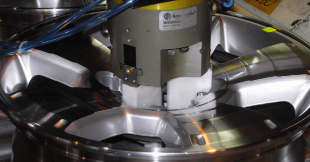
- Clean Environment: Common in medical, pharmaceutical, electronics and food production operations where only very minute amounts of airborne or surface contaminants are allowed, the focus here is to keep any grease or contaminant on or in the gripper from being released into the work environment to avoid contaminating the part or process. Look for a gripper that is Clean Room-certified and approved for Clean Room environments. Scavenge ports used on many grippers help prevent contaminants from the air gripper escaping into the environment. These low-level vacuums create a negative pressure within the gripper and draw clean air from the outside, preventing grease or contaminants from escaping during gripper operation.
- Contaminated Environment: High levels of dirt, debris, oil and grease that are common in automotive, foundry, machining and general industrial applications can adversely affect the internal workings of the gripper and its operation. Here it is critical to protect the gripper from any external contaminants, such as sawdust, metal shavings, chemicals, etc., to keep the gripper functioning trouble-free throughout its useful life. Purge ports on many pneumatic grippers can have a dual purpose – one for preventing contaminants from entering and a second for lubrication. The purge port located on the gripper body has a channel to the internal mechanism of the gripper. During operation, a small amount of low-pressure air is introduced to keep positive pressure within the gripper housing and prevent contaminants from being drawn into the internal gripper mechanism. The option of incorporating grease fittings to purge dirty grease and/or add new grease to the unit adds another layer of protection for the gripper in extremely harsh operating environments.
3. IS A SEALED GRIPPER OR SHIELDED GRIPPER REQUIRED?
Whether operating in a clean or dirty environment, standard or custom-designed shields (or seals) can be used to reliably deflect debris away from the gripper mechanisms in a dirty environment or help keep grease and internal containments from escaping into a clean environment. Gripper shielding can be made up of a variety of styles and materials, including simple formed-sheet metal components or covers, flexible boots, bellows or lip-style wipers. Shielding may be offered as part of the gripper as standard, optional or as a special request by the end user, who may also add their own shielding as a part of a system integration. Orientation of the gripper in relation to the direction of contaminants striking the unit should be considered to minimize the amount of debris that may contact any moving surfaces or exposed openings.
Pneumatic grippers can be made from a variety of materials and specialized processes. Stainless steel, nickel-plating and hard-coat anodizing can keep surfaces from corroding or debris from sticking that eventually cause the gripper jaws to bind. In clean room or food processing applications, these coatings can also prevent oxidation or bacteria buildup that can be released into the work environment. Various lubrications can be high temperature, food-grade or water-resistant to better handle specific environments or any wash-down maintenance requirements. Pneumatic seals designed to handle extreme temperatures or grit and debris help play a role in shielding. Buna-N (nitrile) is normally considered the industry standard, with Viton® and silicone used for higher temperatures. Metal seals are typically used in grippers for handling extreme heat and/or contamination.
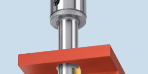
4. WHAT ARE THE KEY GRIPPER SPECIFICATIONS?
Once the demands of the operating environment are understood, the basic gripper design and construction can be considered. A gripper consists of three basic parts: body (including means of power transmission), jaws and fingers. Generally, a gripper manufacturer only designs and builds the body and jaws – known as the “mode of actuation.” Meanwhile, the machine builder or end user supplies the custom fingers to grip or encapsulate the given part. When selecting a gripper, considerations for any application should include appropriate finger length, noting that excess finger length can cause a gripper to bind. When considering grip force, too much will damage the part and too little will drop parts. On gripper stroke, too much is wasted operation time and too little will incorrectly grip or release parts. A wide variety of gripper actuation times will impact the throughput rate of a process. Repeatability is more important than accuracy in general and becomes a key specification when picking up very small objects, i.e. a syringe needle, or working in a high-precision application where one object is being placed inside another object for assembly.
The gripper manufacturer normally publishes these specifications for any given model and their application engineers should be consulted if attempting to operate a gripper outside its performance specifications. They have insights and knowledge of its performance characteristics and tradeoffs, along with an ability to align gripper function to the application and budget.
5. WHAT TYPE OF JAW-SUPPORT MECHANISMS SHOULD I CONSIDER?
Specific application demands indicate which type of gripper jaw-support mechanism to consider. Various grippers may be the same size and perform the same function, but have completely different designs, with some being better than others for diverse operating environments. It is important to align the right mechanism to the application to ensure reliable and accurate actuation of the gripper. From an application point of view, common jaw-support mechanisms include:
- High-Impact Loading Application: Use a plain or wedge-type bearing design identified as a large sliding surface contact bearing. These include flat surface-to-surface bearings and cylindrical bushing-type bearings. A wide bearing surface area is ideal for withstanding continuous high-impact loading applications over a long period of time. This type of mechanism maintains a high degree of accuracy when machined to tight tolerances and provides excellent jaw support. Typically, there is zero to limited adjustability to compensate for gripper wear over time.
- Low-Friction High-Accuracy Applications: Use a line-contact roller-bearing gripper design. These low-friction bearings include cross-roller bearings and Dual V bearings. The bearings supporting the jaws can be pre-loaded to achieve very high accuracy. This bearing system is easily maintained with external pre-load adjustability. Use in applications that require zero side play of the gripper fingers over the life of the gripper. This low-friction design can also allow an easy method of “dialing in” grip force by adjusting air pressure.
- Low Air Pressure Precision Applications: Use a point-contact ball bearing design. This mechanism can operate at very low air pressures where a smooth consistent motion is critical. An added benefit is reduced grease splatter from the gripper as it operates.
The type of bearing used and the amount of surface contact employed in the bearing design determines some key characteristics of a gripper, such as its ability to operate at very low air pressure, impact resistance, repeatability and wear patterns over time, and if gripper wear can be compensated for through bearing pre-load adjustability.
6. WHAT MODE OF POWER TRANSMISSION IS NEEDED?
The mode of power transmission refers to the linkage and transfer of power from the internal air piston(s) to the gripper jaws that open and close, producing a grip force. Overall, a gripper uses a mix of bearing styles with power transmission designs to create the right performance parameters for a wide variety of applications. Here are some general guidelines to follow:
- High Grip Force to Gripper-Size Applications require high grip force, but are constrained by the system’s working space and can require a double-sided wedge gripper design that provides a large surface area for transmitting power to the jaws with the power equally divided between both. This style usually features a single-piston design capable of a high ratio of grip force to size. The gripper jaw/finger motion is inherently synchronized without requiring any additional components. The double-sided wedge is very rugged to withstand high impact loads that may be imparted back onto the mechanism.
- Cost-Effective Parallel-Gripper Solutions. A direct drive design uses a pin or rod to direct couple the piston to the jaw. This is your basic gripper design, a simple, cost effective and easy to shield twin-piston design that requires a jaw-synchronizing linkage.
- Cost-Effective Angular-Gripper Solutions. Many angular grippers use a cam-driven design with direct, synchronized power transmission and bearing-line contact for sending power to the jaws. This has one pivot point per jaw with a minimal number of moving parts. The cam can generate mechanical advantage, resulting in a gripper with high grip force in a relatively small overall package. The cam is commonly used in angular-jaw-motion grippers, but can be found in other types as well.
- High-Precision High-Repeatability Applications. The smooth synchronous operation of a rack-and-pinion transmission is very popular for precision applications because it produces minimal wear on the drive components for long durability. A rack and pinion machined to tight tolerances will produce zero to very little jaw play when installed, and makes it very easy to build a non-synchronous jaw gripper.
7. WHAT ARE THE BEST FINGER DESIGNS AND GRIPPING METHODS?
Gripper finger designs should prevent dropping a part under loss of air pressure whenever possible. Perform a safety analysis to minimize risk of injury or system damage in the event of a dropped part. Pay special attention to the material used for the fingers and the gripping surface of the product. Fingers can easily leave grip marks on the product. To avoid this, nylon, Delrin®, plastics and other soft materials can be used for the fingers instead of aluminum and steel. For fragile parts, urethane pads can be placed on the finger to increase gripping friction without imparting any undue force that may damage the part. Users have numerous gripping methods to consider, including:
- Friction Grip is the most common method, with contact surfaces that close and stop on the part, creating a frictional force that holds the workpiece. If air pressure is lost at any point, the part will drop unless the gripper has built-in safety mechanisms. Friction fingers should be avoided when handling oily or greasy parts.
- Cradled Grip. The fingers are constructed so that they profile the part being handled, i.e., round to round. The fingers close and apply grip force pressure on the part as if it is in a cradle. If air pressure is lost, the part is typically held in place. If the weight of the part is significant enough to offset the backdrive force required to open the gripper, then the fingers may possibly “cam open” due to gravity, allowing the part to drop.
- Encapsulated is generally considered the most secure means of gripping. The fingers have a profile of the part, i.e. rectangle to rectangle, and they close and stop on or even just near the part and rely on the encapsulation to keep the part in position. This is normally considered the safest design because if air pressure is interrupted, the part will not drop unless acted on by an external force.
8. WHAT ADDITIONAL SAFETY FEATURES SHOULD BE CONSIDERED?
Safety is paramount in the design and operation of any gripper component. In the event of power failure that causes loss of operational air pressure, there are other means of preventing a part from accidentally releasing from the gripper and potentially causing bodily injury or damage to part or machine. One option is the use of an internal spring to bias the piston and maintain finger/jaw position on or around the part. Take care to ensure that the spring force is adequate. A second option is using external failsafe valves added to the ports to check air to the gripper in the open or closed position. A third option is the use of rod locks that automatically clamp on the guide rods of the jaws when air pressure is lost. Some, but not all, gripper styles can support the installation of rod locks
The right size and type of gripper can only be specified after all options are considered. Should there be any question of suitability for a gripper to an application, contact the manufacturer. Let them validate the gripper performance requirements to the allocated budget and save you time in researching the myriad of solutions.
Subscribe to learn the latest in manufacturing.


Industry News