Compensation for Dimensional Accuracy in Laser Tube Cutting
This is now a defining element in laser tube processing as shops compete within narrower pricing margins to meet product demands for improved quality and enhanced features. Here’s why.
Posted: June 28, 2019
As market trends change and manufacturing costs continue to rise, fabricators strive to optimize output while reducing waste (losses). Improving part quality while maintaining productivity is ever more critical as end-user needs evolve. Besides material, labor and other production-related costs, laser tube processing operations must also reckon with other elements, such as tube profile shapes, tube sizes, intricacy and position of hole geometries, part quality requirements, production volume, secondary processes and factory workflow. Full production-scale laser tube cutting machines attempt to address and manage these issues within their standard working cycles: Past the programming and nesting phase, the most-accepted working cycle of these machines includes bar loading management (bundle or single bar), length measurement, centering and clamping, compensation, optimized cutting, and finished part and scrap management. At the very least, these are the required functions.
Compensation for dimensional accuracy is becoming one of the most important factors in laser tube processing as designed part tolerances grow more significant and manufacturers continue to compete in improving product quality at various levels of the supply chain system. Let’s discuss the significance of the Compensation Cycle and how it affects the manufacturing process.
THE CHALLENGE
Generally, alloys are standardized globally by a few organizations, the most popular ones being the Aluminum Association (AA), American Society of Testing and Materials (ASTM), American Iron and Steel Institute (AISI), and Society of Automotive Engineers (SAE). Their acronyms are used to specify common metal alloys. Nevertheless, a tube that complies with any of these commercial standards does not necessarily meet dimensional accuracies for laser cutting processes. Tubular steel is characterized by thickness and shape irregularities that are commonly defined by the amount of bow and twist. This is due to residual stress in the material created during the process of manufacturing tube/pipe from steel that is rolled flat, coiled/uncoiled, formed, welded and quenched. Common commercial specifications allow some amount of bow and twist. Even with tubes that are milled with tighter dimensional tolerances, some expected irregularities exist that vary throughout the length of the tube.
Furthermore, additional movements of the workpieces during transportation, lifting, and automatic movements inside the laser machine can contribute to additional sagging in the material. Depending on the diameter and wall thickness of the tube and how well it is supported throughout the machine during movements that include rotations with scimitars, steady rest, intermediate supports, rollers, centering posts and chuck, there could be added material sagging or flexing that widens the existing dimensional tolerance range of the tube. This is why considering how accurately and how quickly the machine handles compensations during the cutting process and how it allows the operator/programmer to define the desired positional accuracy of holes is a very important factor in laser tube cutting.
COMPENSATION
Most laser tube cutting machines utilize the cutting head with integrated height sensors or touch probes (capacitive sensors or Renishaw probe) in order to compensate for bow and twists in the material. During the compensation cycle (before cutting), the head probes the tube surface at several points and takes a series of measurements. This process can take several seconds depending on the amount of twist detected in the tube, adding significant time to the production cycle.
LIMITATIONS OF TRADITIONAL COMPENSATION METHODS
The primary limitation set by standard probe sensors is the amount of time they add to the part cycle time. If the amount of twist varies along the tube’s length, a single measuring cycle may not be sufficient. This increases the amount of time the machine takes to verify the dimensions quite significantly, because the head has to probe various faces and corners over the entire bar to determine the tube’s geometry. This could reduce productivity and limit the machines output significantly, especially in parts that have multiple and intricate geometries. Another issue is that touch probes cannot compensate successfully when cutting non-round shapes due to the inconsistency in the shape and the differences in corner radii. For example, in square or rectangle-shaped tubes, the last corner that is formed during the milling process turns out differently from the others. Since touch probes simply measure with distance sensors on the outside surface of the material, it becomes difficult to analyze profile variations in the tube. This also becomes more significant when processing open and special shape profile materials.
Some manufacturers have employed a method of rotating the lunette against the chuck in order to straighten the tube during the cutting process. However, this is not efficient for two major reasons:
- The material tends to spring back to its original form when released.
- It could cause pre-mature wear on machine components.
AN OPTICAL MEASURING DEVICE
The most acknowledged solution to the bow and twist compensation challenges is a patented camera-assisted optical measuring device known as Active Scan that provides some significant advantages over traditional probe sensors, including:
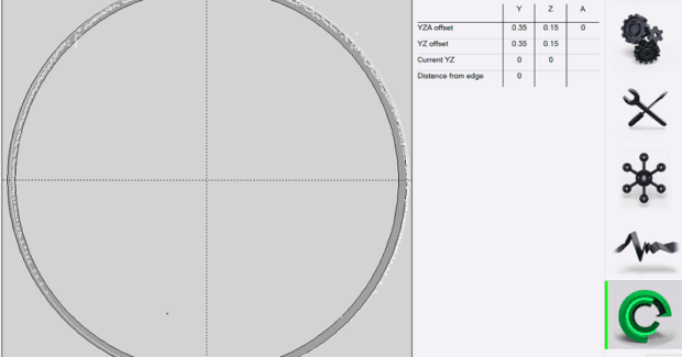
- Speed. The system scans and analyzes the profile of the tube in less than one second per scan. This is substantially faster when compared to probe sensors. The system compares the scanned profile of the tube to the theoretical shape and provides a visual representation of the comparison between the actual and theoretical shapes on the machine control, along with the detected section error and detailed compensation offsets that have been performed (see Figure 2).
- Programmability: Active Scan provides a method for the programmer/operator to define and control the accuracies that are important to maintain. For example, in some cases accuracies should be defined based on hole-to-hole relationships, while in other cases it could be based on hole-to-surface relationships, such as centering a hole on one face, regardless of other geometries or irregularities. Despite the surface or edge of the tube that geometries may be placed on, the system maintains and analyzes the scanned data to compensate according to the accuracies defined by the operator/programmer. Besides geometric relationships, the system also allows the user to customize the frequency of scanning based on features that require higher accuracy.
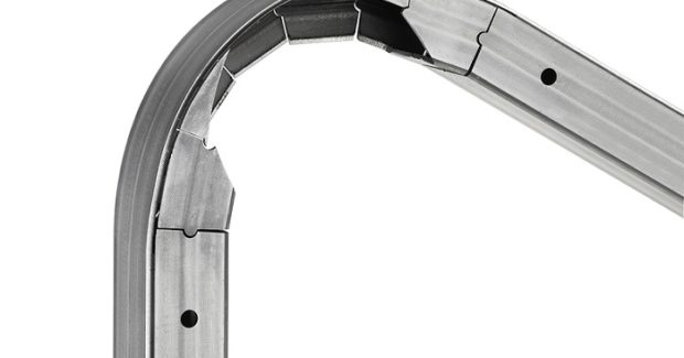
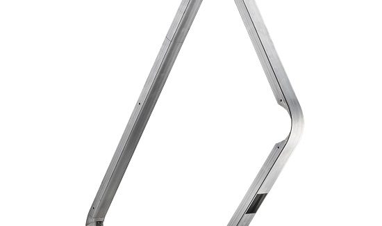
- Tube Profile Analysis: Since the system scans the profile of the tube and compares it to the theoretical shape, it can analyze the difference in corner radii or angles and positions the laser-cut features according to the desired accuracy, despite the differences in the corner radii. A good part example would be a cut-bend sequence shown in Figure 1. Figure 2 also shows the profile analysis.
- Compensation Report: Active Scan provides a detailed report of the compensations and offsets of each production by material, along with graphical data that can be printed and used for data analysis by fabricators. The amount of compensations and offsets that are performed are indicative of the cumulative reduction in productivity.
In summary, the method of accuracy measurements and compensations must be taken into account during the laser cutting process, as well as understanding how the method of compensation affects overall efficiency (including part quality) and productivity. Compensation for accuracy is now a defining element in laser tube processing as shops compete within narrower pricing margins to meet product demands for improved quality and enhanced features. It is evident that the supply chain system – ultimately fueled by ever changing end-user needs – is dictating the need for fabricators to possess advanced manufacturing capabilities that allow them to effectively adapt and meet those changes.


