How to Troubleshoot Five Common Robotic Welding Issues
The problem may be as simple as a loose contact tip or something more complex, like incorrect TCP. Understanding the steps for proper troubleshooting helps narrow down potential causes, prevents replacement of components that don’t need replacing, and quickly gets you back to producing quality parts.
Posted: February 18, 2019
Every operation wants to avoid downtime and its associated cost for troubleshooting problems in a robotic welding cell. But sometimes issues happen, whether it’s due to equipment failure or human error. Since most shops invest in welding automation to boost throughput and profitability, getting an automated welding cell back online as quickly as possible is critical to production and the bottom line. The first things to consider are whether anything has changed in the welding process or with the equipment, or if the operator has recently reprogrammed the robot. In many cases, evaluating the most recently changed variable can help you pinpoint an issue’s cause. After that, analyzing some of the most frequent sources of trouble in the robotic welding cell can help you get to the root of the problem sooner. Consider these five common issues and ways to fix them:
WHAT CAUSES POOR CONSUMABLE PERFORMANCE?
The material being welded and the parameters being used affect consumables’ longevity. But if it seems that nozzles, contact tips, diffusers or liners aren’t lasting their typical life or are performing poorly, there could be several causes. Check all connections between the consumables and tighten them as needed. A loose connection increases electrical resistance and generates additional heat, which can shorten consumable life and cause poor performance. It’s especially important to ensure consumables are properly tightened when the application involves long welds or welds on thick materials, since any rework due to quality issues will cost more time and money in these cases. Common contact tip issues, such as burnback, are often caused by a too-short liner. Always follow the manufacturer’s instructions for liner trimming and installation, and use a liner gauge to confirm length when possible. Over time, debris and spatter buildup inside the liner can contribute to shortened contact tip life. It’s important to create a schedule for changing liners, just as you would for other consumables.
If you’re frequently experiencing weld defects like porosity or lack of penetration, this can also stem from a consumables issue. Make sure the contact tip and nozzle are free of debris and replace them as needed.
WHAT CAUSES POOR WIRE FEEDING?
Erratic or poor wire feeding in robotic welding is a common issue that can ultimately result in poor weld quality. Poor wire feeding can have many causes: Cutting a liner too short is particularly problematic when robotic welding with smaller diameter wires, which have less column strength. Extreme articulation of the robotic MIG gun can also lead to poor wire feeding. Program the robotic MIG gun cable to stay as straight as possible. The robot may not weld quite as fast, but proper gun orientation helps minimize downtime for feeding problems. Excessive conduit length and multiple bends or junctions can cause poor wire feeding as well. With the drive rolls open, you should be able to pull the wire through the contact tip by hand with minimal effort. If you need to pull with two hands or put your bodyweight into the process, that indicates interference with the wire path between the wire drum and the contact tip. Check for bends tighter than 90 degrees, multiple junctions between sections of conduit or worn conduit sections that can increase drag on the wire. Ideally, the conduit between the drum and the wire feeder should be less than 20 ft, with no junctions or tight bends.
Improper drive roll selection and tension setting can also lead to poor wire feeding. Consider the size and type of wire being used and match that to the drive rolls. Inspect drive rolls for signs of wear and replace them as necessary.
WHY IS THE CABLE PREMATURELY FAILING?
Whether you have a through-arm robotic welding system, where the cable is routed through the robotic arm, or a standard over-the-arm robotic welding system, premature power cable failure can happen. A power cable that becomes kinked or worn can fail and short-out against the robot casting, leading to costly repairs. To help prevent premature cable wear, consider the programmed path of the robot as well as the power cable’s length. If the robot’s movements cause the cable to bunch up or kink, it can cause the power cable to fail. If the power cable rubs against tooling or catches on components during the programmed cycle, this can also cause premature failure. Proper cable length is also important. A cable that is too short or too long can be stretched beyond capacity or be prone to kinking.
WHY IS THERE A PROBLEM WITH TOOL CENTER POINT?
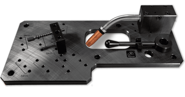
In robotic welding, tool center point (TCP) refers to the location of the end of the welding wire with respect to the end of the robot arm. If you are experiencing inconsistent welds or welds that are off-location, this may stem from a problem with TCP. If the robotic MIG gun neck is bent or damaged during a collision in the weld cell, this can result in TCP issues. Use a neck-checking fixture or neck alignment tool to help ensure proper angle of the neck bend. Also, be sure the neck and consumables are installed and torqued properly. Failure to do so may affect TCP. However, a problem with off-location welds isn’t always caused by TCP issues. Improper fixturing or part variations may also be the root cause. If a TCP check using the robotic program turns up with no issues, a part or position variation is the likely culprit.
HOW DO I FIX POORLY PERFORMING PERIPHERALS?
Companies often implement peripherals, such as reamers or nozzle cleaning stations, to optimize robotic welding performance and get more life out of consumables. But a problem with the reamer can cause spatter buildup on the consumables. Reamers can perform poorly for three common reasons:
- Improperly taught position of the robotic MIG gun nozzle in relation to the reamer. This position should be concentric to the cutting blade on the reamer at the proper insertion depth to ensure thorough cleaning of the nozzle.
- Too much or too little anti-spatter spray in the wrong location. Anti-spatter spray should cover the inside of the nozzle and the outside should be covered within ¾ in from the bottom of the nozzle. Spray for only a half-second. In production, the anti-spatter should evaporate on contact with a hot nozzle – if your nozzle is dripping, you’re spraying too long.
- Using the wrong cutting blade or improper insertion depth will not allow for proper removal of accumulated spatter.


