Five Frequently Asked Questions on How to Improve MIG Welding
Use these answers to refresh and refine your skills and take your MIG welding operation to the next level.
Posted: October 24, 2018
MIG welding, like any other process, takes practice to refine your skills. For those newer to it, building some basic knowledge can take your MIG welding operation to the next level. Or if you’ve been welding for a while, it never hurts to have a refresher. Consider these frequently asked questions, along with their answers, as welding tips to guide you:
1. WHAT DRIVE ROLL SHOULD I USE AND HOW DO I SET THE TENSION?
The welding wire size and type determines the drive roll used to obtain smooth, consistent wire feeding. There are three common choices: V-knurled, U-groove and V-groove. Pair gas- or self-shielded wires with V-knurled drive rolls. These welding wires are soft due to their tubular design; the teeth on the drive rolls grab the wire and pushes it through the feeder drive. Use U-groove drive rolls for feeding aluminum welding wire. The shape of these drive rolls prevents marring of this soft wire. V-groove drive rolls are the best choice for solid wire. To set the drive roll tension, first release the drive rolls. Slowly increase the tension while feeding the wire into your gloved hand. Continue until the tension is one half-turn past wire slippage. During the process, keep the gun as straight as possible to avoid kinking the cable, which could lead to poor wire feeding.
2. HOW DO I GET THE BEST RESULTS FROM MY MIG WELDING WIRE?
MIG welding wires vary in their characteristics and welding parameters. Always check the wire’s spec or data sheet to determine what amperage, voltage and wire feed speed the filler metal manufacturer recommends. Spec sheets are typically shipped with the welding wire, or you can download them from the filler metal manufacturer’s website. These sheets also provide shielding gas requirements, as well as contact-to-work distance (CTWD) and welding wire extension or stickout recommendations. Stickout is especially important to gaining optimal results. Too long of a stickout creates a colder weld, drops the amperage and reduces joint penetration. A shorter stickout usually provides a more stable arc and better low-voltage penetration. As a rule of thumb, the best stickout length is the shortest one allowed for the application.
Proper welding wire storage and handling is also critical to good MIG welding results. Keep the spool in a dry area, as moisture can damage the wire and potentially lead to hydrogen-induced cracking. Use gloves when handling the wire to protect it from moisture or dirt from your hands. If the wire is on the wire feeder but not in use, cover the spool or remove it and place it in a clean plastic bag.
3. WHAT CONTACT RECESS SHOULD I USE?
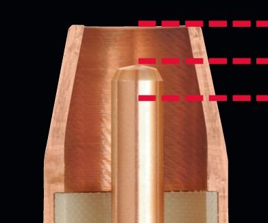
Contact tip recess, or the position of the contact tip within the MIG welding nozzle, depends on the welding mode, welding wire, application and shielding gas you are using. Generally, as the current increases, the contact tip recess should also increase. Here are some recommendations:
- A 1/8 in or ¼ in recess works well for welding at greater than 200 amps in spray or high-current pulse welding, when using a metal-cored wire and argon-rich shielding gases. You can use a wire stickout of 1/2 in to 3/4 in during these scenarios.
- Keep your contact tip flush with the nozzle when welding less than 200 amps in short circuit or low-current pulse modes. A ¼ in to ½ in wire stickout is recommended. A ¼ in stickout in short circuit, specifically, allows you to weld on thinner materials with less risk of burn-through or warping.
- When welding hard-to-reach joints and at less than 200 amps, you can extend the contact tip 1/8 in from the nozzle and use a ¼ in stickout. This configuration allows greater access to difficult-to-access joints, and works well for short circuit or low-current pulse modes.
Remember, proper recess is key to reducing the opportunity for porosity, insufficient penetration and burn-through and to minimizing spatter.
4. WHAT SHIELDING GAS IS BEST FOR MY MIG WELDING WIRE?
The shielding gas you choose depends on the wire and the application. CO2 provides good penetration when welding thicker materials and you can use it on thinner materials since it tends to run cooler, which decreases the risk of burn-through. For even more weld penetration and high productivity, use a 75 percent argon/25 percent CO2 gas mix. This combination also produces less spatter than CO2 so there is less post-weld cleanup. Use 100 percent CO2 shielding gas or a 75 percent CO2/25 percent argon mix in combination with a carbon steel solid wire. Aluminum welding wire requires argon shielding gas, while stainless steel wire works best with a tri-mix of helium, argon and CO2. Always reference the wire’s spec sheet for recommendations.
5. WHAT IS THE BEST WAY TO CONTROL MY WELD PUDDLE?
For all positions, it is best to keep the welding wire directed toward the leading edge of the weld puddle. If you are welding out of position (vertical, horizontal or overhead), keeping the weld puddle small provides the best control. Also use the smallest wire diameter that will still fill the weld joint sufficiently. You can gauge heat input and travel speed by the weld bead produced and adjust accordingly to gain better control and better results. For example, if you produce a weld bead that is too tall and skinny, it indicates that the heat input is too low and/or your travel speed is too fast. A flat, wide bead suggests too high of heat input and/or too slow of travel speeds. Adjust your parameters and technique accordingly to achieve the ideal weld, which has a slight crown that just touches the metal around it.
These answers to frequently asked questions only touch on a few of the best practices for MIG welding. Always follow your welding procedures to gain optimal results. Also, many welding equipment and wire manufacturers have technical support numbers to contact with questions. They can serve as an excellent resource for you.


