Scanning vs. CMM
The long-established technology of coordinate measuring machines is now being challenged in myriad applications by the fast-emerging, highly advanced science of blue light scanning.
Posted: February 17, 2018
For over 50 years, the benchmark for accuracy in measuring solid objects, whether machined, molded, die cast, welded or forged, was the coordinate measuring machine (CMM). Typically using a solid granite base table along with a vertical, horizontal, gantry or bridge-mounted arm and touch probe, measurements would be taken and compared in blocks to an engineering file, first as 2D drawings and now as CAD files hosted in the cloud. But during the last two decades, a “new kid in town” has arrived on the scene with power, size, point capability and price value that are rapidly leaving CMM technology in the dust: 3D laser scanning, plus the latest trend of industrial CT scanning that is based on the same technology used for medical MRI, permit an array of points to be read, both external and internal, on a wide variety of substrates and manufacturing techniques.
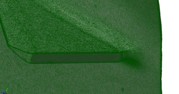
3D scans are made on many types of metals, composite, thermoplastic, elastomeric, wood, fiber and fabric materials, while CT scanning permits internal exploration of a thick aluminum casting, injection molded plastic or rubber parts, even prepared foods, packaging, archaeological finds and fine art. The old joke is that “with CT scanning we all would have known about Venus de Milo’s arm problems long before they occurred.” CT scanning can produce results for porosity, dimensional, failure analysis, volume and fiber orientation, all while leaving the part undamaged. In contrast to conventional tactile CMM techniques, laser and especially CT scanning captures all surface points simultaneously on even the most complex, convoluted surface areas. Where a typical touch probe might capture 300 points of reference for comparison to a CAD overlay, the laser or CT will capture millions of points. Typical systems can now offer measurement accuracies to 4+L/100µm referring to the VDI 2630 metrology guideline.
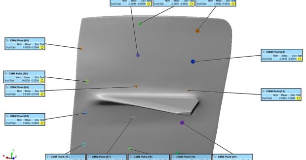
Consider this recent example: An engineer was boasting of having produced the “perfect part” based on CMM deviation points. His shop had used our scanning services in the past. We performed a quick blue light 3D scan on the object and quickly determined the part was out of spec on several faces, as certain critical points had been missed in the CMM protocol. Our millions of scan data points were fit to the deviation map and the problem was tracked backed to the production source and rectified. Now his shop is a regular user of scanning. This example does not indicate CMM technology has outlived its usefulness by any means. We continue to use it in our operations for certain measurements in many applications. One important point to note is that the same software that manipulates the data from the CMM can be used with 3D scanners and CT equipment alike.
In terms of the data created, the 3D scanning produces color maps, inspections, first article inspections or other outputs. What a shop does with the data after completing the scanning is endless. On the topic of substrates, it should be noted that CT scanning now offers the ability to evaluate a wide variety of dual thickness and dual density materials, with disparate examples ranging from an automotive firewall that might have differing thermoplastics, or rubber and TPE materials co-molded to a candy bar with chocolate and nuts.
There are substantial cost savings to be realized in the purchase of a 3D scanning device or the new generation of table top CT scanners, depending on the parts being examined, making the transition from CMM to 3D or CT is more economically feasible. There are two driving factors for evaluating the service vs. purchase issue: The easier factor is raw cost, where a 3D scanner is typically half the cost of a CMM for measuring comparable part sizes. The other factor is more complex, namely the talent of the personnel doing the work. Experienced technicians have the ability to scan and process large data sets on a wide variety of substrates, geometries and part sizes effectively. Coupled with the part volumes being processed and other factors, it is often more practical and profitable for a shop to use a scanning service on an as-needed basis.
An additional point to note in evaluating CMM vs. scanning is the time involved. To derive those 300 touch points referenced above might take four hours on a CMM, while the 2.5 million points derived from a 3D scan would take 30 minutes. Since Polyworks software can be used on a CMM or 3D laser scanner, the time and money savings quickly accumulate. Plus, in this manner, shops can develop something of a “universal metrology” scenario by augmenting the existing CMM technologies with 3D and even CT scanning capabilities, making their QC department more powerful from the outset. One practical note: Training QC, R&D and production department personnel usually takes three days or less to expand their capability from CMM to include 3D and CT scanning.


