The Competitive Edge of Simulating Hybrid Operations
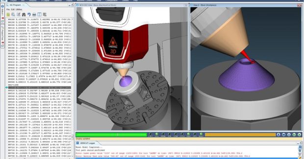
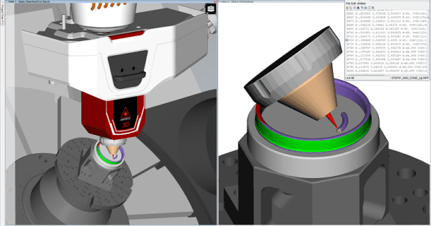
Realistic simulation of the entire hybrid process enables users to verify that the part will be built correctly, without causing damage to the part, machine, or expensive laser equipment. This enables shops to gain a competitive edge by choosing the best manufacturing strategies for creating, customizing and/or repairing products – all while redefining their current production technology to create new possibilities.
Posted: January 10, 2018
For the small job shop with simple parts to the OEMs and Tier 1 suppliers that regularly push the limits of CNC technology, version 8.1.2 of VERICUT® CNC machine simulation, verification and optimization software suite enables users to eliminate the process of manually proving out NC programs on all types of CNC machine tools.
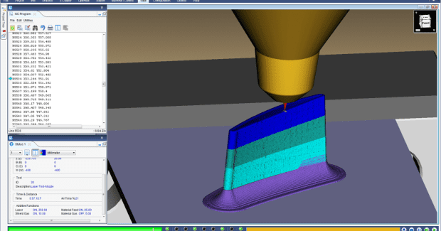
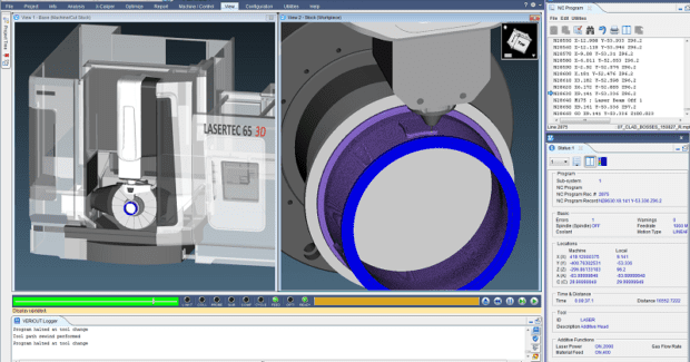
This powerful, easy to use software reduces scrap loss and rework and optimizes NC programs in order to both save time and produce higher quality parts that are dimensionally more accurate with better surface finish. The Additive module simulates the same post-processed NC code that drives both the additive and traditional machining capabilities of hybrid CNC machine tools, and simulates both additive and traditional CNC machining capabilities applied in any order. This enables shops to virtually experiment with combining additive and traditional “subtractive” metal removal processes to determine optimal safe hybrid production methods.
Simulating hybrid operations gives shops a competitive edge to create, customize and/or repair products, and in the process, redefine their current production technology to create new possibilities. They can choose the best manufacturing strategies for their parts. Realistic simulation of the entire hybrid process enables users to verify that the part will be built correctly, without causing damage to the part, machine, or expensive laser equipment. This includes the ability to identify problems that can occur when integrating additive methods and solve AM challenges, such as accurate laser cladding and material deposition, detecting collisions between the machine and additive part, and finding errors, voids, and misplaced material. Simulating both operations also gives the user access to detailed history that is stored by using unique droplet technology that saves programmers time by quickly identifying the source of errors with a single click.
In the Additive module, additive material deposition is seen in Reviewer and NC Program Review. Additive errors and red error color are applied to deposited material when any of the additive functions being checked are not compliant, making it easy to spot potential problems in additive processes. A single click identifies the error source. The Section window makes it easy and fast to see inside a part during simulation. This allows the user to check proper fit and identify interference between the workpiece and machine components. Sectioning abilities in machine view help with complicated machines where visibility is challenged. Enhancements allow the simulation to be continued while sectioned, and zoomed to achieve unobstructed viewing to pinpoint highlighted errors.
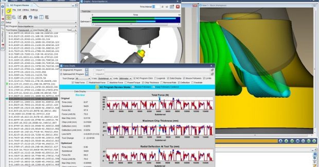
Using Force™ Optimization and OptiPath, shops can optimize more complex NC programs, including looping, branching, IF/THEN and DO-WHILE code, while retaining all decision-making logic. Optimized NC programs and subroutines are ready to run with no edits by the user. The Force module is a physics-based NC program optimization method that maximizes chip thickness and creates more constant cutting forces, resulting in significant machining time savings. Force Charts that graphically document the cutting process are enhanced with higher fidelity so that they can display even tiny material volumes and forces encountered. They are displayed in real-time, revealing cutting conditions and forces as they are encountered by cutting tools. The data helps NC programmers identify undesirable cutting conditions represented as spikes in the graphs.
Spikes display forces, chip loads, tool deflection, and material removal rates above the recommended parameters. With one click on the chart, the exact location in the NC program is marked while the actual cut in the graphics window is displayed. By optimizing toolpath feed rates, Force reduces machining time, prolongs tool life, and produces a higher quality finished product. In the Teamcenter Interface module, Tool Manager imports 3D cutting tools from Siemens Teamcenter® Product Lifecycle Management (PLM) software. VERICUT connects directly to Teamcenter to reference files, avoiding the need to create external uncontrolled copies of models on a local or network drive. In the NX CAM project, all cutting tools used in a given project are listed. In one step, all 3D cutting tools for a job are imported at once.
The X-Caliper measuring tool creates a measurement label on the part, and label placement is customizable for optimal viewing. Multiple dimensions can be displayed on the part to quickly document key measurements, create setup diagrams, or inspection aids. Images with dimensions are easily referenced in reports, and the Report Template editor makes creating a custom report easier. Adding content directly to the report editor is simplified using standard word processing capabilities and standard HTML objects. The template editor displays what the report will look like as the template is designed to shorten the design process.
Version 8.1.2 includes many other features, such as the Grinder-Dressing module where users can simulate dressing where a secondary tool is applied to a grinding wheel to freshen the grinding surface, or to change the grinding wheel cutting shape. The software simulates the dynamic compensation needed while the dresser is used, even while the grinder is engaged with the part. The software also has the ability to stop at specific variables when they are set or changed.


