Next Steps in CAD/CAM Applications
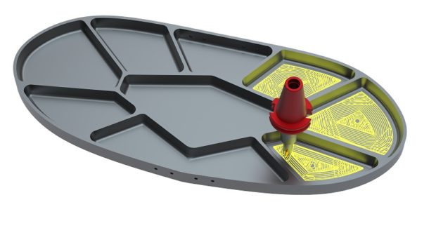
Waveform Roughing in Vero Surfcam from DM Solutions ensures that a constant volume of material is removed for high speed machining of harder materials by using as much of the flute length as possible to distribute wear evenly along the entire cutting length, rather than just the tip.
Posted: May 12, 2017
In Booth 5446, Vero Software reseller DM Solutions Inc. (Derry, NH) will display their Surfcam computer-aided-manufacturing (CAM), the Part Modeler 3D modeling tool, and the WorkXplore high-speed CAD file viewer and analyzer. Surfcam Milling provides functionality to program wire frame geometry or solid model component parts on a variety of machine tool configurations, from 2.5-axis milling to complex surface tool paths on 3-axis to 5-axis milling machines. It offers intuitive dialogs, making programming simple for the new user and comprehensive tool path control for advanced requirements. Now available in Surfcam for both milling and turning is the Waveform Roughing strategy, a high-speed machining technique that maintains a constant tool cutting load by ensuring that tool engagement into material remains consistent. The toolpath moves in a smooth path to avoid sharp changes in direction, which maintains the machine tool’s velocity.
Waveform Roughing greatly improves on standard roughing by ensuring that a constant volume of material is removed. This paves the way for high-speed machining, particularly for harder materials. Using as much of the flute length as possible distributes wear evenly along the entire cutting length, rather than just the tip. The radial cut depth is reduced to ensure consistent cutting force, allowing cut material to escape from the flutes. Tool life is extended, as most of the heat is removed in the chip. Other rough milling cycles available in Surfcam deliver a variety of toolpath control and methods, and include lace, concentric and spiral. Shape recognition allows sub routines to be applied with a simple check box. Surfcam then produces the required toolpath and tool entry into the material. It will recognize changes in geometry and create sub routines as appropriate.
Part Modeler comes complete with fully associative drafting capability, and provides advanced modelling tools to create parts or workholding systems such as chuck jaws or fixtures. The major features of a machine tool can also be modelled, for accurate cutting simulation and collision detection. With the ability to execute a series of logically grouped construction operations as a single keystroke, Part Modeler enables rules to be applied simultaneously across multiple parts of an assembly with automatic part-to-part compatibility. Full associativity is maintained across 2D and 3D drafting, isometric, plan and orthogonal views, standard and ordinate dimensioning, and geometric tolerancing. The intuitive user interface can be quickly and easily tailored to individual requirements, with features such as dockable windows and customizable menus and toolbars that ensure a highly productive, smooth and seamless progression from design concept through to finished component model and detail drawing. Tighter integration between engineering and manufacturing paves the way to increased productivity.
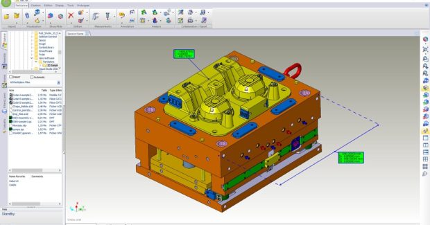
WorkXplore offers a powerful combination of full-feature capabilities, high overall functionality, and speed. It was developed to increase collaboration, productivity and effectiveness in cross-functional product development, including design, process development, manufacturing, quality, sales and customer communication, purchasing, product documentation, and more. WorkXplore enables the creation of all kinds of measurements on 3D parts and offers advanced analysis features that allow users to determine undercut areas, plane surfaces, thicknesses, volumes, surfaces, weight, and to perform dynamic cross-sectional visualization.
Two-dimensional drawings are no longer necessary, as users can directly add dimensional and geometric measurements, annotations and labels to the 3D model. WorkXplore also allows users to communicate 3D parts and assembly files to sub-contractors, customers or colleagues via a stand-alone and extremely compact application that can be easily transmitted via the Internet. The recipient can immediately display and work on the 3D model received.
The software features a set of tools for simplifying and optimizing 3D model processing, ranging from 3D file comparison to relatively simple or complex cinematic animations and exploded views. Three new capabilities in the 2017 edition of WorkXplore maintain the powerful high speed CAD viewer and analyzer’s long tradition of updating format support and new enhancements. It contains many innovative features usually found in high-end CAD systems that enable users to perform part diagnostics, create assembly instructions and prepare the production of 3D models. The software, which can open the native files of Edgecam, VISI and WorkNC, was created to efficiently import and analyze all file types and sizes at high speed. It often takes less than half the time to open a file compared to the original CAD application. The main new items of functionality for the new WorkXplore 2017 R1’s translators are:
- 3D PDF support for mesh writing
- JTOpen support for mesh writing
- Reader and writer support for MEG files.
It is now possible to write solid and mesh models into the 3D PDF and JTOpen formats, and the resulting files contain mesh entities. Solid and mesh models can also be exported in the MEG format used by Vero Software’s production machining CAD/CAM solution, Edgecam. In addition, MEG files can be imported into WorkXplore. The translators support most file formats, including DXF/DWG, IGESW, Inventor, Parasolid, SolidWorks, Rhino, Pro/E – Creo, several versions of Catia, and several others. As well as the enhancements to the translators, updates have been made to WorkXplore 2017 R1’s curvature analysis. The object being analyzed can now be displayed with colors corresponding to curvature radius values defined as ranges. New radius values can be added and edited interactively, and colors can be displayed in either flat or gradient mode. The software now comes with the option to show or hide toolbar button captions, meaning it is now possible to choose whether the toolbar button captions are displayed or not. The option is set in the application parameter window.
DM Solutions, Inc., 4 Tinkham Avenue, Derry, NH 03038, 603-434-4516, www.dm-solutions.com.


