Using Shielding Gas Efficiently
Gas handling equipment is one area shops sometimes overlook to keep costs down to stay competitive. Proper gas-saver flowmeter regulators can ensure saving on the amount of shielding gas that is used with each pull of the trigger of the welding gun.
Posted: August 26, 2016
It is no secret that managing the costs of materials used in metal fabrication is key to staying profitable in the business. Shops must take advantage of every opportunity to keep costs down to stay competitive. Gas handling equipment is one area they sometimes overlook. The cost of a cylinder of shielding gas is one component in the equation, how efficiently the gas is used is the other. Understanding the role that efficiency plays requires a closer look at the function of the individual component pieces and the dynamics of gas delivery control systems in action.
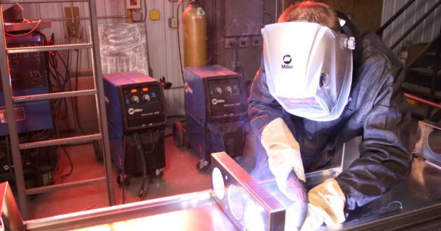
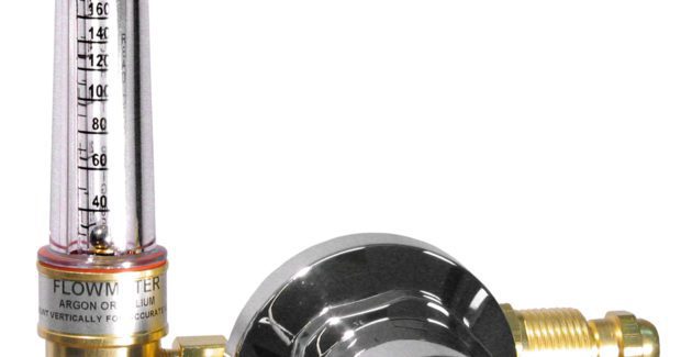
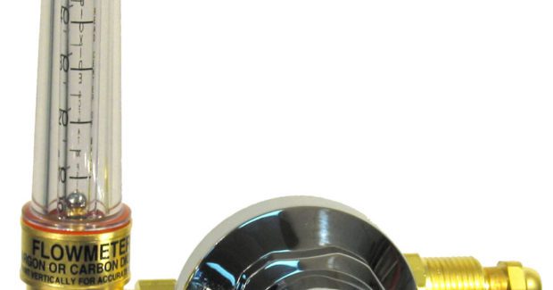
Shielding-gas flowmeter regulators are used in cylinder gas and pipeline applications for Metal Inert Gas (MIG) and Tungsten Inert Gas (TIG) welding to provide an oxygen-free environment around the weld puddle that facilitates the joining of the two parts together (Figures 1, 2). Gas flow is typically measured in volume over a given time period in standard cubic feet per hour (scfh) or, more commonly, cubic feet per hour (cfh). The two most common ways to control flow involve fixed and varied pressure. In the first, you use a set or fixed pressure to a flowmeter from a regulator with an adjustable outlet valve on the flowmeter. Cylinder or pipeline pressure is reduced and sent to the flowmeter, and the outlet valve on the flowmeter is adjusted to control the flow into the weld puddle at 30 scfh to 50 scfh, at 30 psi to 50 psi compensation pressure.
This system is called a compensated flowmeter. The flow tube is normally marked with the gas service or services, and the fixed or compensated pressure is also listed on the tube. Different manufacturers have different compensated pressure set points 30 psi to 50 psi. It is germane to the discussion here to point out that we set the compensated pressure on standard industrial gas regulator flowmeters to 30 psi to help eliminate wasted gas.
The second method to control gas flow is to use a fixed outlet orifice and vary the pressure to the flowmeter. This is a non-compensated flowmeter that must be used in conjunction with an adjustable-pressure regulator. The pressures generated by the regulator to achieve the flows required are typically between 5 psi to 10 psi. The wasted gas in TIG and MIG welding processes is generated from the high compensation pressures used in compensated flowmeters, usually 50 psi. The 50 psi-compensated flowmeter is common because the flow tube is usually the most expensive part of the flowmeter. Most welding flowmeter manufacturers have standardized on the 40 psi to 50 psi compensation points. It is worth noting that the higher psi-compensated flowmeters are the most common — and the biggest gas-wasters.
These 50 psi-compensated units build a reserve of gas into the supply system that creates a surge when the gas solenoid is activated and the welding process has started. It is common to see gas surges of up to 120 cfh with the flowmeter only set to deliver 30 cfh. These surges fall from 120 cfh to the set flow of 30 cfh in three to five seconds. This initial burst of gas is all wasted gas until the system equilibrates to the set flow. The amount of gas that is wasted is dependent on the frequency that the solenoid is activated: the more activation, the more wasted gas. If the solenoid were activated only a few times a day, there would be only a small amount of wasted gas. In typical industrial applications, activations are frequent, rendering gas waste high.
Non-compensated flowmeters are capable of delivering 30 cfh of gas at approximately 5 psi. With 5 psi versus 50 psi, the surge is reduced to almost none. These non-compensated flowmeter regulators are the best option for gas savings. Gas-saver flowmeter regulator models will normally save up to 20 percent of the cost of shielding gas. While the low-pressure non-compensated flowmeter regulators are most often the gas-savers of choice, there are applications in which a compensated unit may be required. When long lines from the flowmeter to the gun may cause back-pressure or wind may cause the shielding gas to blow off, the compensated system may be the solution to these problems. While the gas-savers may not fit every application, they do work well in most welding applications.
Some gas-saver models have lockout features that prevent the user from increasing the flow of the gas through the flowmeter by the lockout on the adjustment knob on the regulator. The lockout option ensures that the flowmeter cannot be adjusted so the system can be set to a flow providing more gas than required. In the minds of many welding operators, if the job requires 30 cfh, then 60 cfh is better. This mindset will also waste gas, even if gas-savers are employed. It’s important to note that when selecting flow control equipment, the equipment itself is only purchased once, but the gas is purchased often. Quality gas-saver flowmeter regulators ensure saving on the amount of shielding gas that is used with each pull of the trigger of the welding gun.


