Closing the Loop: Strategies for Bending Closed Forms
With a bit of creativity and thought to overcome limitations, it is often possible to form closed profiles and other difficult parts with a standard press brake. Here are some tips on how to do it.
Posted: August 25, 2016
One of the great advantages of sheet metal as a raw material is its malleability, or ability to stretch, twist and bend without breaking. From a basic sheet of flat stock, metal components can be manipulated into a staggering array of useful shapes. One of the most common tools for shaping sheet metal is the press brake, and any fabricator wanting to turn raw metal into finished products is likely to use one out of necessity. Although press brakes are incredibly versatile, they do have limitations. The achievable shape is limited by the available tooling as well as the force and length capacities of that particular press brake. The tooling required to form a bend and the frame of the machine are also physical obstructions that the metal must work around. This common limitation is the primary reason why certain metal shapes, such as deep boxes or channels, can be particularly difficult to produce.
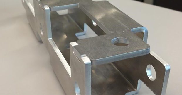
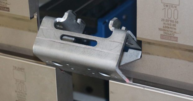
Another difficult – if not impossible – shape to produce with a press brake is a completely-closed form where the piece of metal is bent in such a way that the material returns on itself with no gap or opening left at the end. Although completely-closed profiles present unique challenges, certain methods can be used to circumvent physical obstructions on a press brake. To start with, if there is some flexibility in the design of the component, a bit of clever engineering can make the job much easier. Figure 1 shows a square, tubular profile that is formed from a flat part using a press brake with standard tooling. Strategic placement of holes allows this profile to be closed with good quality and without any tooling collisions. Despite the additional holes, the finished product is strong, rigid and could be used as a load-bearing structural piece. Jigsaw-style tabs interlock during the final bending operation to add strength to the part and create a seam that is easy to weld if additional rigidity is required.
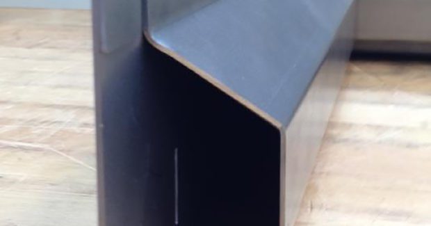
Another design method that enables production of a looped profile is to utilize a hem or fold in the material to close the finished component. Figure 2 shows a fabricated steel window frame produced with this method. The essential point in this type of design is that the fold or hem is formed as the very last operation, and in the course of closing up the hem, the rest of the part profile is pulled together. This type of design provides the added benefit of a very rigid finished product, and like the tube profile in Figure 1, it can be fabricated with standard press brake tools, eliminating the need for costly custom designed options.
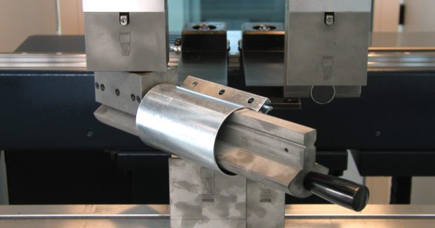
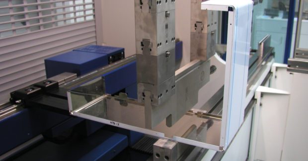
Although both of these profiles show how applying a little design-for-manufacturing knowledge can make a complex component easier to produce, there are many situations where this approach would not be possible. Perhaps the design of the component cannot be modified because the finished product cannot have holes or folds in it. Whatever the reason, it is time to turn to the press brake tooling for a solution. The simplest alternative is to use a pair of “horned” press brake upper tools. Most manufacturers already have a set of these tools in their inventories. Horned tools are typically placed outward at the ends of a press brake tool station so a box or tray with return-flanges can be formed without a collision. However, if you take two horned punches and reverse them so that the horns face inward instead of outward, you can create a press brake tool with a gap or “window” that a metal part can form through (Figure 3).
The limitation to this type of tool setup is immediately obvious: the width of the loop you are looking to close is limited by the size of the window that the tools create. Generally speaking, this setup enables an operator to bend a closed profile one or two inches wide maximum. In addition, there is no straight-forward way for the press brake operator to remove the closed profile once it has been formed through the tools. It is necessary to unclamp the upper tools and slide them apart in the machine so the finished product can be removed. This means the process will be fairly slow and probably not well-suited to high volume production, but for prototyping or low volume production it can be a viable solution that is easy to implement.
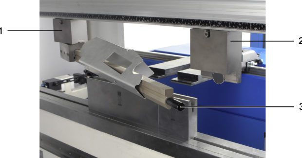
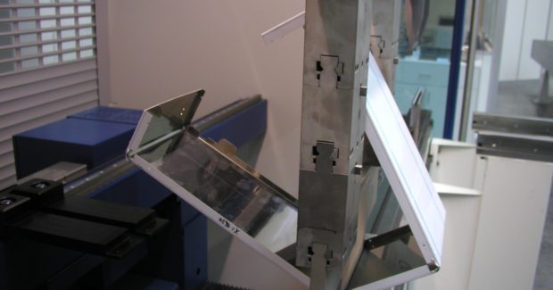
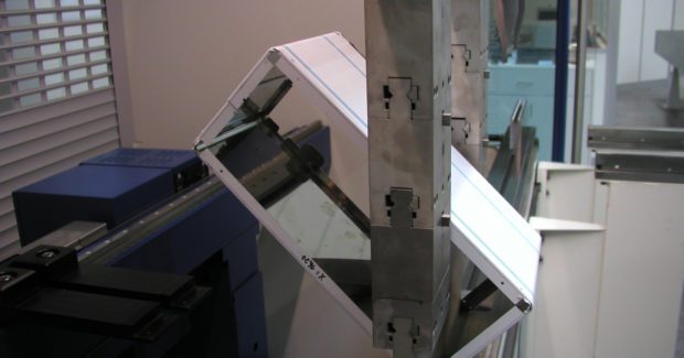
For higher production volumes, or closed profiles that are wider than a couple inches, there are specialized press brake tools available to do the job. One very handy example is known as a “slewable window tool” (Figure 4). This custom press brake tool consists of a pair of upper tool holders, connected by a bar, to create a large window. The bar is attached to one of the tool holders by a pivoting hinge, and the other end is held in place by a magnetic clasp. This tool allows a closed profile to be formed around the bar and then removed by releasing the magnetic clasp, pivoting the bar outward, and easily sliding the finished product free of the tool assembly. The operator simply must re-clasp the bar and start bending the next part. This tool confers the advantage of being able to form longer closed profiles up to a couple of feet in width while also delivering fast cycle times. The limitation is the strength of this type of tool. Since its design is not nearly as rigid as a solid tool, operators are limited to a much lower tonnage capacity which limits it use to fairly thin materials.
Although it might take a bit of creativity and thought to overcome limitations, it is often possible to form closed profiles and other difficult parts with a standard press brake. Start by considering how a redesign could make the part easier to produce. Next consider existing resources as a potential low-budget, easy to implement solution until production requirements warrant a higher-end more efficient approach. Above all, never hesitate to call in application support for some expert advice!


