CAD/CAM Software Improves Automation, Machining and Feature Extraction
Alphacam 2016 R2 from Vero improves machining performance with enhanced feature extraction and automated management of part geometry.
Posted: June 20, 2016
A number of new and enhanced items in the latest release of Alphacam software by Vero Software (Gloucestershire, UK) provide improvements with automation, machining and feature extraction. Alphacam 2016 R2 also contains a range of general improvements, along with new user interface commands for faster and simpler ways of working.
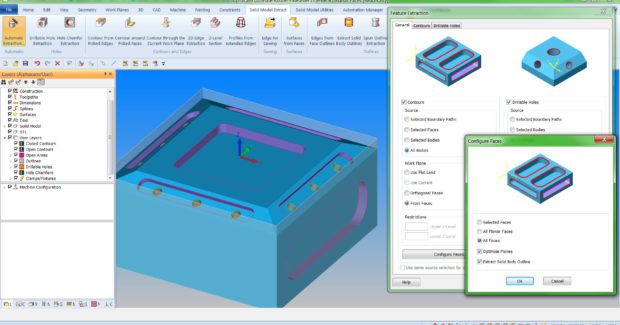
For example, Alphacam Clipboard enables entities to be cut, copied and pasted in the Drawing Area between different versions of the software open on the same PC. An additional option has been added for pre-drilled holes as the entry type on waveform roughing operations. A new method has also been added for extracting contours in work planes by selecting faces to create the work plane for the extraction direction. “This improved feature extraction on user-selected multiple angled faces is a real time-saver,” said Michael Pettit, the EMEA sales manager. “Feature Extraction has also been enhanced using an updated algorithm for finding contours.”
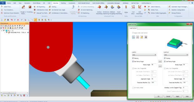
Some machining dialogs now have a new tab containing specific options for either 2D or 3D lead-in and lead-out paths, and there is also an option to save and open user-configured lead settings in addition to the defaults. It’s now possible to copy all settings both ways between the lead-in and lead-out section. Another new option achieves tool angle direction entry into a part when machining features such as grooves and slots. The Selecting Sloping / Ramp Angle in the Lead-In/Out dialogs provides access to this new function. When this checkbox is ticked, it can be set to the same angle as the tool in the aggregate holder.
There are also changes to the separate standalone dialogs used for editing the leads of existing operations. Both the 2D and 3D versions of these dialogs – which are accessed by right clicking in the Project Manager – now have an apply button for previewing leads before accepting changes. The Project Manager Insert page now contains commands for automatically inserting files in user-configured positions when they’re dragged into the Drawing Area. Additional dialogs create ‘new’ and ‘edit existing’ configurations that can be selected from either the screen or user layers, specifying one or more snap points.
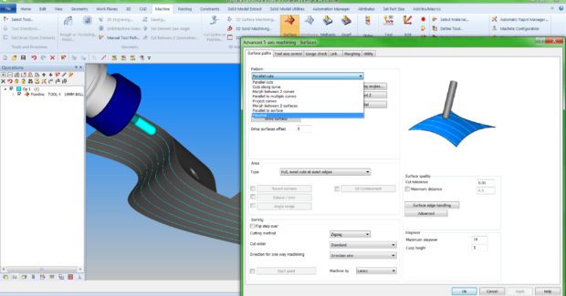
A new surface machining pattern has been added to the advanced 5-axis cycle. Flowline creates a toolpath aligned to either the U- or V-direction of the machining surface. The user can determine the toolpath style, choosing the direction of the surface parameter lines. As only a single face is required, calculation is extremely fast. A typical application for Flowline is where a specific surface texture or grain is required. Also with 5-axis, the progress bar showing machining has been improved to give more feedback during complex toolpath calculations.
AUTOMATION MANAGER
A number of updates to the powerful Automation Manager include changes to Job Settings, Machining Order, Layer Mapping, and added support for nesting small parts into defined zones:
- Job Settings: When adding new files to a job, Automation Manager sets parameters for Layer Mapping Setup, Material and Machining Order to ‘From Job’ by default. They can be overwritten if necessary, for a particular file.
- Machining Order: The new Machining Order tab replaces the former Tool Ordering tab, defining the order of machining operations. The order lists are associated with layer mapping setups and machining styles . . . and multiple machining lists can be configured.
- Layer Mapping: A New Drawing Layer command button has been added to the ribbon bar in the Layer Mapping Setup tab enabling users to create layers manually, and add layer names without having to import them from a drawing.
- DXF/DWG Import Support for Z Levels from Parallel Planes: The Layer Mapping Setup tab has a new import option for DXF, DWG and Alphacam drawings and functions, meaning that parts which would have had work planes are simplified to Auto Z, and can be nested correctly.
- Added Support for Nesting Small Parts Into Defined Zones: After drawing a sheet and adding it to the sheet database, parts can be defined as small parts for nesting zones by using the new Small Nested Part option in the Processing tab.
GEOMETRY
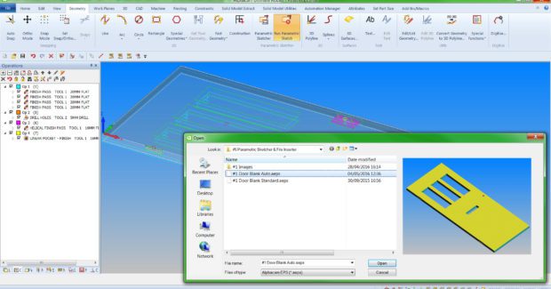
Among many changes to how Alphacam 2016 R2 handles geometry, new ribbon bar command buttons have been added to the Parametric Sketcher dialog, enabling users to associate an image with Parametric Sketches (.aeps) and Variables (.aepsvars). The associated images will be displayed in the Project Manager Insert page. Another benefit is that the dialog displayed when using the Run Parametric Sketch command is resizable and a toggle button switches between the associated image and preview.
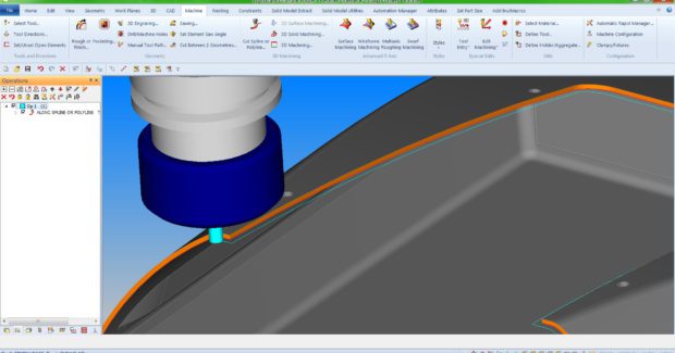
Enhancements have been made to the Cut Spline/Polyline command for the machining of sharp internal and external corners. A new option within the Panelling command function now automatically closes geometries in each panel by creating geometry elements along the panel edges. Processing time is reduced when creating a simplified version of a detailed model where roughing paths do not require a high level of detail. Using the 3D / STL Utilities / Simplify command, the number of facets in a model can be reduced as a percentage of facets in the original. This simplified STL model either replaces the original or is created in addition to it.
Vero Software, Hadley House Bayshill Road, Cheltenham, Gloucestershire, GL50 3AW, United Kingdom, +44 (0) 1189-756084, www.verosoftware.com.


