Considerations When Selecting a Filler Metal (Part One)
Filler metal selection is critical to maintain the integrity of the final weldment. Here is a review of their general properties that can help you determine which filler metal is ideal for the job.
Posted: December 1, 2015
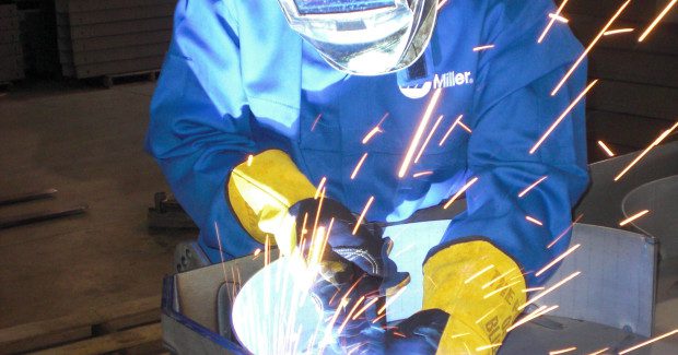
Having the right filler metal for the job can have a significant impact on quality, productivity and cost. Different filler metals provide varying mechanical and chemical properties — but in every case, the welds they create must be able to withstand the service conditions they will encounter. There are numerous factors that contribute to the decision when selecting a filler metal. In this first installment of a two-part series, we learn about the considerations for making the best choice.
FACTOR ONE: THE BASE MATERIAL TO BE WELDED
Matching the chemistry of the filler metal to that of the base material is the first consideration when selecting a welding wire or stick electrode. If the chemistries match, the mechanical properties (such as the tensile, toughness and yield strength) will also match. That means the welding operator can feel confident knowing that the weld deposit will have the same strength and properties as the base material.
In cases where the materials being joined are not the same strength, there are other considerations. As a rule of thumb, welding operators should match the strength of the filler metal to the lower strength of the two base materials. Dilution from the higher strength base material during the welding process is typically sufficient to strengthen the weld metal deposit.
https://youtu.be/kNRS6zA8Jkk
A welding operator usually knows what type of base material he or she is working with. When that’s not the case, most base metals can be easily identified through tests based on appearance and reaction to magnets, chisel, fracture and flames or sparks. It may be necessary in some cases — usually during repair or rework welding — to take a sample to a lab for chemical analysis. It’s also important to consider the base material’s shape, thickness and general condition to help determine the appropriate filler metal. When in doubt, contact a trusted welding distributor or filler metal manufacturer for assistance in making the selection.
FACTOR TWO: THE WELDING POSITION
Positioning the part so it can be welded in a flat position is preferred whenever possible. It is always the most economical and efficient way to weld, followed by horizontal, vertical and, lastly, an overhead position. The filler metal chosen must be appropriate for the position in which the welding operator will be welding.
When the application involves a large weldment that cannot be manipulated, it requires the welding operator to weld in multiple welding positions. This out-of-position welding can be especially challenging if there is only one wire size available. For example, a vertical weld up using a 3/32 in diameter wire may be extremely difficult or even impossible. A better choice for that weld would be to use a wire ranging from .045 in to 1/16 in diameter. Note that such a change requires setting up an additional wire feeder or another power source to accommodate the different wire size. It would also require a change in drive rolls and possibly the welding gun.
The need to change welding positions during a job can slow the process and compromise efficiency, so it’s an important consideration to keep in mind. When possible, select a filler metal type and size that allows for the most versatility.
FACTOR THREE: REGULATORY SPECIFICATIONS AND CODES
In many cases, job specifications dictate what class of wire to use. In applications where this is not the case, welding operators should carefully consider the service requirements the weld may encounter. Using a mild steel filler metal for applications exposed to harsh elements, for example, makes it more likely the weld will rust, deteriorate and corrode at a faster rate than the base material. That could lead to weld failures, which is especially detrimental when the end product is used in critical applications such as a pressure vessel in high-temperature environments or a bridge exposed to the elements.
Whichever filler metal a welding operator uses, it must meet the service condition of the final product to ensure the weld deposit lasts as long as the base material. In applications that require welding to code, it’s equally important that the filler metal meet the qualifications or certification of that code. Filler metal manufacturers can provide information regarding the codes and/or product approvals to which their products are usable.
SELECTION IS CRITICAL
Filler metal selection is critical to maintain the integrity of the final weldment, so it’s worthwhile to take the time to make the right match. Although the effect of various elements in filler metals can be rather complex and inter-related, a review of their general properties can help welding operators determine which filler metal is ideal for the job. For additional information about how to select the best filler metal, consult a welding equipment distributor or trusted filler metal manufacturer.
Coming up next time in the second part of this series, we learn about additional factors that impact filler metal selection, including design requirements, shielding gas and welding equipment. Don’t miss it.


