Understanding Sheet Distortion During Punching
Sheet bowing is a common problem, but also predictable and therefore able to be addressed.
Posted: June 2, 2015
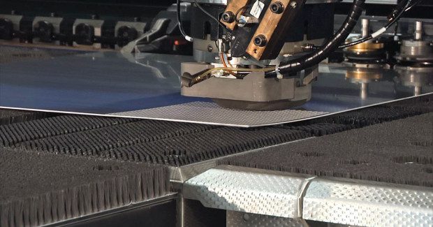
Any fabricator who has punched a large number of holes in sheet metal has dealt with sheet distortion, namely bowing. Bowing is problematic as it creates a higher risk of collision between the sheet and punching head, which may result in machine damage and wasted material. Whether the part is completed on the punching machine, or further processed on a press break, a secondary operation, such as rolling, is needed to flatten the workpiece. This increases the cost-per-part as it requires additional equipment, man power, and time to get the part out the door. Take a few minutes to recognize the factors at play during distortion and some solutions to counteract it.
THE PUNCHING PROCESS
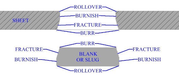
To understand sheet bowing, consider the stages of the punching process (see Figure 1). First, the tooling contacts the sheet and when the applied force surpasses the material’s yield strength, the material plastically, or permanently, deforms. Since the bottom die pushes up with the same force as the punch traveling downward, plastic deformation occurs at the top and bottom surfaces of the sheet and is referred to as rollover.
Next, the cutting begins. The punch and die are forced into the workpiece, creating a penetration zone known as the burnish region. Friction between the sheared edges and the tooling make this area shiny, smooth, and straight. The size of the region is dependent on the ductility of the sheet metal and the clearance between the punch and die. When punching force is high, cracks propagate from the ends of the burnish region. Cracks created from the punch above and the die below eventually meet to form the fracture zone. The fracture zone has a dull, rough, and angled appearance and as with the burnish region, its size depends on the ductility of the metal as well as the punch and die clearance.
In the final step a burr is created as the metal elongates during final separation of the sheet. Burr height increases with larger die clearances, softer metals, and dull tools.
CAUSES OF BOWING
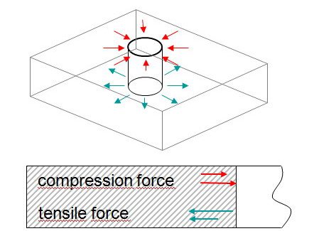
Sheets begin to deform for two reasons. The first involves strains, or material displacement, induced by the punch and die in the immediate proximity of a punching operation. These strains are a result of the plastic deformation, or rollover, in conjunction with the fracture. To plastically deform, residual stresses must exist within the sheet that prevent the material from returning to its original position. Figure 2 shows the two types of residual stress in a punched hole.
For bowing to occur, the magnitude of the tensile stress created as the material is pushed out through the bottom of the sheet must be greater than the compressive stress created as material is drawn into the punched hole. Since the stresses do not spread across the entire sheet, a highly worked part may exhibit bowing while the remaining skeleton stays flat.
The severity of bowing depends on a number of factors. The amount of punching in the part is one of the most obvious. As processing increases, so does the stress on the part which, in turn, intensifies bowing. The thickness of the material is a second factor. Thicker sheets exhibit greater rollover and require more force to produce a punched hole. The additional force also increases sheet deformation. Stronger materials require greater tonnage for punching as do tighter die clearances. The result, again, is increased bowing. Dull tools are also problematic. If a tool is not sharp, the amount of rollover increases and greater force is needed to create the hole.
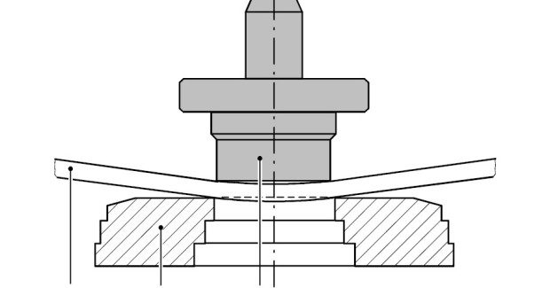
In addition to strains in the material caused by punching, bowing also occurs as the material bends during processing. When the punch contacts the material, the sheet deflects into the die (see Figure 3). The top of the sheet is in compression while the bottom is in tension. These strains and stresses lead to bowing.
WAYS TO COUNTERACT BOWING
Luckily, there are ways to address sheet distortion. Two easy solutions are to keep punches and dies sharp and set to the proper die clearance. Be mindful of die clearance since a large clearance can negatively impact the burr height and the overall quality of the hole. Additionally, fabricators can use the tool’s stripper to hold the material flat while it is being machined. On some punching machines this is called the presser foot.
Before the punch contacts the sheet, the presser foot clamps the material against the die. The punch completes its downward stroke through the material and returns to operating height. The stripper then rises, releasing the material, and the table moves to the next position to repeat the process. When processing soft materials, be aware that the presser foot may actually cause the sheet to bow. If the machine allows it, simply decrease the stripper pressure to eliminate this concern.
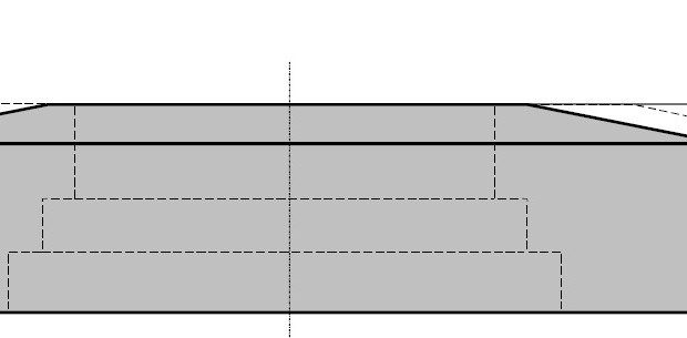
A more experienced fabricator can use different tooling options in conjunction with the presser foot to backbend the sheet over the die. The idea is to combat stress imparted by the punch and die by introducing opposite stresses with the stripper. Balancing forces is very important because if the stripper pressure is too high, bowing in the opposite direction can occur. A classic way to backbend the material is by using domed or chamfered dies (see Figure 4).
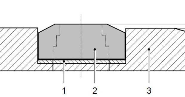
The raised surface on the die allows the stripper to backbend the sheet by exerting pressure around the outside edge of the die. Our customers with standard tooling and the smaller die version can also create this effect. A raised surface is generated with shims to elevate the die above the die adapter (see Figure 5).
By using a stripper with an opening slightly larger than the die itself, backbending is achieved. Bowing in the opposite direction can occur if the die is shimmed too high, the presser foot pressure is too great, or a combination of the two. Another solution, unique to our equipment, is the integrated flattening option. As with the solutions above, backbending is achieved; however, the process uses specialized tooling and is wholly controlled through variables in the machine control.
A final method to reduce sheet deformations is pre- and post-punching. Here, the area of strain in the sheet is punched off. To prevent the formation of new strains in the sheet it is important that the post-punch process removes very little material. Sheet bowing is a common problem, but also predictable and therefore able to be addressed. Consider the application, the tooling available and your machine capabilities to best counteract this issue for jobs that run through your shop.
Subscribe to learn the latest in manufacturing.


