Direct Load Position Sensing with Secondary Feedback Encoders
To help verify machine tool accuracy in closed-loop motion control systems, direct load monitoring using secondary feedback encoders eliminates common sources of position error — mechanical backlash, non-linearity, and hysteresis — and saves money along the way.
Posted: March 5, 2014
EFFECTS OF MECHANICAL WEAR AND TEAR OVER TIME IN ROTARY ENCODER SYSTEMS
Once the system is in operation, mechanical failures can result in large indicated position errors that might go undetected until bad parts are produced. For example, a drive belt might slip or jump a tooth, a shear pin might break, or a rack-and-pinion gear might wear enough to slip out of synchronization. In these cases, the shaft-mounted rotary encoder has no way of knowing that the nominal relationship between shaft revolutions and load position has been completely invalidated.
MOTION CONTROL SYSTEM ARCHITECTURE DEFINES LIMITS OF SYSTEM PERFORMANCE
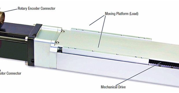
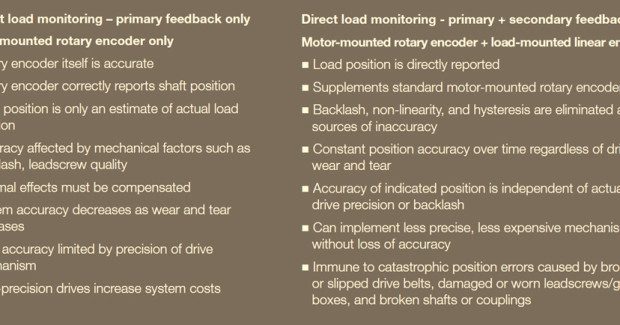
This motion control architecture in which a rotary encoder is coupled to the shaft of the drive motor is an example of indirect load monitoring. By locating the position encoder at the back end of the drive system instead of at the load itself, the system accuracy is inherently limited by the imperfections of the mechanical drive system.
A BETTER WAY: LINEAR ENCODERS AS SECONDARY FEEDBACK
An alternative architecture for closed-loop motion control systems eliminates or minimizes the influence of any nonlinearity that may exist in the mechanical drive system. By simply relocating the primary position data collection point from the motor shaft to the linear motion axis itself, drive-system stack-up errors can largely be ignored. Bear in mind, however, that extremely sloppy mechanisms are always hard to tune.
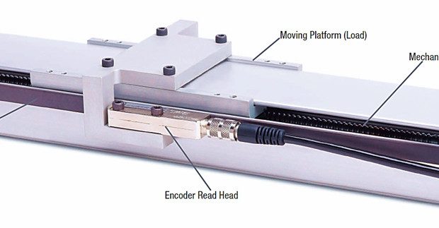
In this arrangement, motor shaft revolutions do not need to be directly proportional to load position, because the linear encoder is now directly reporting load position. This system architecture — where a secondary linear encoder is located along the controlled motion axis — is an example of direct load monitoring.
ADVANTAGES OF DIRECT LOAD MONITORING USING SECONDARY FEEDBACK
Direct load monitoring offers several economic and performance benefits. For starters, the indicated load position is not affected by mechanical factors such as backlash, dynamic compression or tension, drive wear and tear, or rotation reversal hysteresis. Nor is linearity compromised by the quality or accuracy of the leadscrew or other drive system components.
By relieving the mechanical drive system of the burden of maintaining overall system accuracy, less precise or lower cost drive mechanisms can be employed as part of the original design. Because wear and tear no longer degrades system accuracy over time, there is no need to build in excessive upfront performance in order to guarantee accuracy over the system’s life expectancy: System designers can save costs by more closely matching initial performance specifications to long-term performance expectations.
With direct load monitoring, the accuracy of the indicated load position is largely a function of the linear encoder’s accuracy. Linear-encoder specifications can be closely matched to application requirements, eliminating unnecessary cost. Direct load monitoring architectures are also largely immune to drive failures that may result in catastrophic position errors. Even if a belt slips or a gear breaks, the indicated position coming from the linear encoder still closely represents actual load position.
EACH ENCODER PLAYS TO ITS STRENGTHS: ACCURATE REPORTING OF SPEED AND POSITION
The motion controller now has two independent sources of dynamic feedback: the rotary encoder mounted on the motor, and the linear encoder mounted on the moving load. The rotary encoder still provides an excellent source of data regarding the speed and direction of the motor itself. This is very important information that is needed by the motion controller to ensure precise control of position and velocity of the driven load.
At the same time, the secondary feedback provided by the linear encoder provides rock-solid position data as well as speed and direction. The combination of these two data sources allows the motion controller algorithms to deliver motion that is smooth, accurate, responsive, and adaptable to varying loads.
MONITOR MECHANICAL DRIVE WEAR AND TEAR
By comparing the indicated positions of the rotary and linear encoders to one another, the motion control system can monitor mechanical drive wear and tear over time. As the drive begins to exhibit increasing play and slop, the amount of deviation between the two readings will increase and provide valuable information for preventive maintenance and predictive failure. If and when catastrophic mechanical failure occur, the large differential between the rotary and linear encoder readings provides instant notification of the problem.
A NOTE ON THERMAL EFFECTS
Heat affects all mechanical positioning systems. Indirect load monitoring systems are subject to position error from thermal growth or contraction of the leadscrew. Controllers can partially correct for these effects with known expansioncoefficient values, but direct load monitoring does not require this compensation; as motion axis components (and the work piece itself) expand with increasing temperature, so does the linear encoder.
If the thermal expansion coefficient of the linear encoder closely matches the coefficient of the drive components and work piece, no relative position error is introduced, and the system is self-compensating with respect to temperature. To this end, many linear encoders are delivered with metallic base materials that closely match the expansion characteristics of the metal surfaces on which they are mounted.


