Variables That Affect Weld Penetration
Which welding variables affect weld penetration? How can you get more or less penetration in a weld?
Posted: January 23, 2014
Q: In your January 2014 column (“Weld Fusion vs. Weld Penetration“), you discussed weld fusion vs. weld penetration, as well as when deeper weld penetration can be beneficial or be a problem. Which welding variables affect weld penetration? How can you get more or less penetration in a weld?
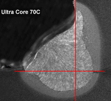
A: Depth of fusion (aka “penetration”) is the distance that fusion extends into the base metal or previous pass from the surface melted during welding. Figure 1 shows a cross section of a fillet weld, where the penetration profile can be seen.
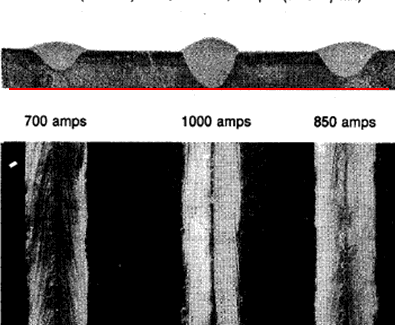
Current, measured in amperage, is the welding variable with the greatest effect on the degree of weld penetration. Quite simply, as welding current increases (i.e. more amperage), weld penetration increases, and as welding current decreases (i.e. less amperage), weld penetration decreases. Figure 2 illustrates this point with three welds made at different current levels and where all other variables were held constant.
With arc welding processes using constant-current output, current is the main, presettable welding variable. However, with processes using constant-voltage output, voltage and wire-feed speed (WFS) are the main, presettable welding variables, with current levels a result of WFS. As WFS increases, the corresponding current level for that particular electrode type and diameter also increases. Conversely, as WFS decreases, current also decreases.
Several other welding variables also affect the degree of weld penetration. The following bullet points, in no particular order, discuss the effects that each variable has on penetration level (assuming that all other variables are held constant). Note that Figure 2 as well as Figures 3, 5, 6 and 7 show cross-sections (and the resulting penetrations levels) of welds made with the submerged arc welding (SAW) process.
The SAW process was chosen to illustrate the effect (or no effect) that these various welding variables have on penetration level because the results are more dramatic. SAW typically is used at very high current levels, as well as rapid travel speeds and fairly high voltage levels, and uses larger-diameter electrodes. While changes in these welding variables have the same effect on penetration level as when using other arc welding processes, because current level and other settings are not as high, the differences in penetration are not as dramatic.
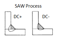
• Polarity: The type of welding polarity used affects penetration level. With most arc welding processes, DC+ (direct current electrode positive) polarity produces more weld penetration, because more arc energy is focused into the base plate. Conversely, DC- (direct current electrode negative) polarity produces less weld penetration, because more arc energy is focused into the electrode and not into the base plate.
This is the case with the shielded metal arc welding (SMAW), gas metal arc welding (GMAW), flux-cored arc welding (FCAW) and SAW processes (see Figure 3). The exception is the gas tungsten arc welding (GTAW) process, in which the effect of polarity on penetration is opposite. With GTAW, DC- polarity results in more weld penetration (DC+ polarity generally is not used).
Some advanced SAW power sources use Waveform Control Technology and alternating current (AC) to provide excellent arc stability and control between weld-deposition rates and weld-penetration levels. They also have the ability to control the balance of the AC wave, offset of current and frequency for further control over the weld characteristics.
• Welding Process: The various arc welding processes have associated weld penetration characteristics. For example, SAW, FCAW and GMAW (in a globular, spray or pulse-spray arc-metal-transfer mode) processes are known in general for higher levels of weld penetration, whereas the GTAW, GMAW-C (metal core) and GMAW (in a short-circuit metal-transfer mode) processes are known in general for lower levels of penetration. Of course this correlation also is related to current.
For example, the SAW process tends to be used at very high current levels while the short-circuit GMAW process tends to be used at lower current levels. The SMAW process can have deeper or shallower penetration characteristics, depending on the specific type of electrode used.
• Type of Electrode: Even within the same welding process, electrodes of different classifications can have different penetration characteristics. For example, with the SMAW process, an E6010 electrode typically has deeper penetration, while an E7024 electrode typically has shallower penetration. Another example can be seen with the FCAW process. An E70T-1 electrode typically has deeper penetration, while an E71T-1 electrode typically has shallower penetration.
• Travel Angle: The degree of the travel angle, whether a push or drag travel angle, affects the amount of arc force directed down into the base plate. A travel angle of 0 deg to 10 deg (i.e. the electrode perpendicular or mostly perpendicular to the plate) results in more weld penetration. As the travel angle becomes more severe, the level of weld penetration decreases.
• Shielding Gas Type: Shielding-gas types also have an effect on weld penetration. Shielding gases with a higher rate of thermal conductivity, such as 100 percent carbon dioxide (CO2) or 100 percent helium (He), produce welds with broader, deeper penetration profiles. Conversely, shielding gases with a lower rate of thermal conductivity, such as 100 percent argon (Ar), or an Ar / CO2 or Ar / oxygen (O2) blend, have a shallower penetration profile that is more tapered in the middle (see Figure 4).
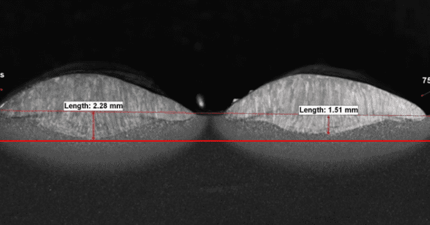
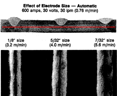
• Electrode Diameter: When welding with two different diameters of the same electrode and at the same current level, more penetration generally is achieved with the smaller-diameter electrode than with the larger-diameter electrode (see Figure 5). If you look at an end slice of each sized wire, the smaller diameter has less cross-sectional area than the larger diameter.
As the same amount of current flows through each electrode, the concentration or density of current is greater in the smaller-diameter electrode than in the larger-diameter electrode. As a result of this higher current density, the smaller-diameter electrode will have greater weld penetration than the larger-diameter electrode. Note, however, that every electrode diameter has a maximum current density before the welding arc becomes unstable and erratic. So as current reaches a certain level, it becomes necessary to increase the electrode diameter.
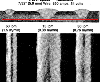
• Travel Speed: How fast the electrode travels down the joint affects how much time the arc energy has to transfer into the base plate at any particular point along the joint. As travel speed increases, the amount of time that the arc is over a particular point along the joint decreases and the resulting level of penetration decreases. As travel speed decreases, the amount of time that the arc is over a particular point along the joint increases and the resulting level of penetration increases (see Figure 6).
• CTWD Variations: With the GMAW, FCAW and SAW processes on constant-voltage power sources and running at a set wire feed speed and voltage, as the contact tip-to-work distance (CTWD) is increased, more resistance to the flow of electricity through the electrode occurs, because the electrode (i.e. the metal electrical conductor) is longer. At a constant-voltage level, this increase in resistance causes current to decrease (i.e. Ohms Law), which results in a decrease in penetration level. Conversely, as CTWD is decreased, resistance also decreases. Therefore, current increases and penetration increases.
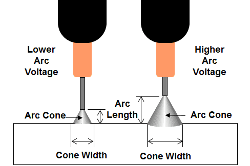
One main welding variable with virtually no effect on weld penetration is arc voltage. While changes in arc voltage can result in minimal changes in weld penetration, the effect is very minor compared to welding current and the other variables listed in this article. Arc voltage affects arc length. At the same wire-feed speed, as voltage increases, arc length increases and as voltage decreases, arc length decreases. The length of the arc in turn determines the width and size of the arc cone.
As arc length decreases, the arc cone becomes narrower and the arc is more focused (see Figure 7). The result is a weld bead that is more narrow and ropy and the level of weld penetration may decrease slightly. Conversely, as arc length increases, the arc cone becomes wider and the arc is broader. The result is a weld bead that is wider and flatter and the level of weld penetration may increase very slightly.
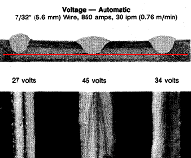
The effect of arc voltage on the bead shape can clearly be seen in Figure 8. Notice also that a slight difference in weld penetration can be detected between welds made at 27 volts, 34 volts and 45 volts (all at the same amperage, travel speed and electrode diameter). Realize, however, that this is an extremely large variation in arc voltage, done only on this weld sample to illustrate the point. Practically, arc voltage would only be varied by a few volts when welding. Therefore, the change in penetration caused by changing voltage (only) by just a few volts is virtually nonexistent.
Ironically, many welders mistakenly think that arc voltage is the main variable which affects the level of weld penetration. Voltage often is improperly referred to as “heat,” where welders turn up the voltage or “heat” for perceived more penetration and turn down the voltage or “heat” for perceived less penetration.
This misconception likely occurs because they see the weld bead widen out with more voltage and become narrow and ropey with less voltage (as illustrated in Figure 8). However, as explained above, the weld-bead profile becomes wider or narrower with changes in voltage because the arc cone becomes wider or narrower with changes in voltage. The resulting weld-penetration level with different arc voltage levels (but at the same current level) is virtually unchanged.


