Choosing a Butt Weld Joint Preparation
Which joint configurations provide the best economy? Here is an examination of the “pro-versus-con” arguments that must be weighed out in order to make an informed decision when choosing between U-groove and V-groove joint preparations and small bevel versus large bevel configurations.
Posted: November 26, 2012
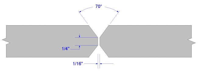
Figure 1. AWS D1.1 prequalified joint B-U3c-S utilizing a bevel and a root opening.
(Click on illustration to enlarge it)
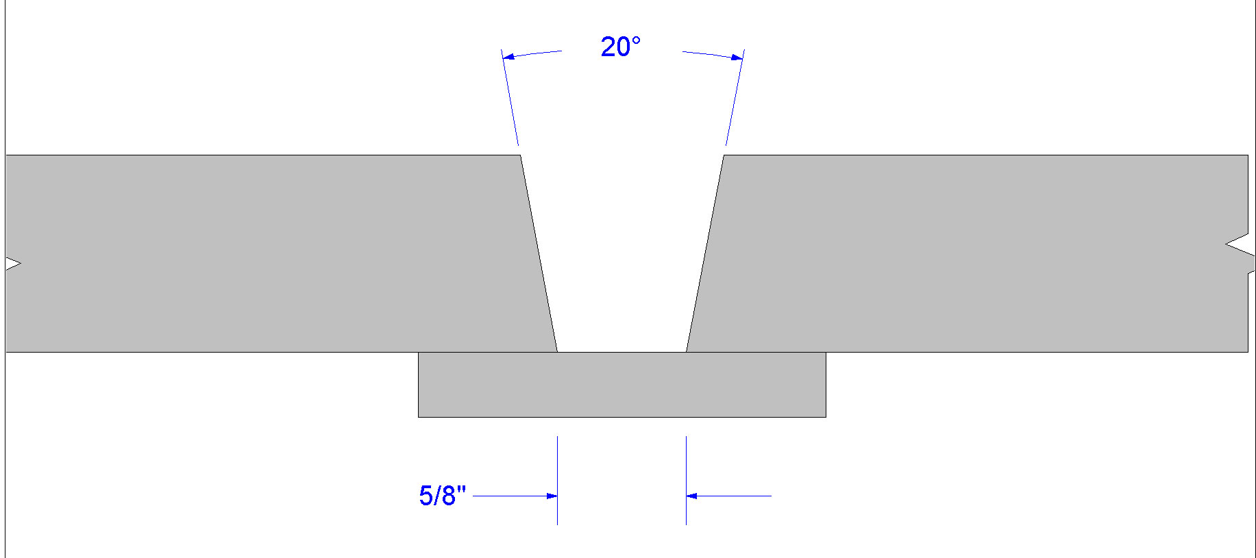
Figure 2. AWS D1.1 prequalified joint B-U2-S utilizing a bevel and a root opening.
(Click on illustration to enlarge it)
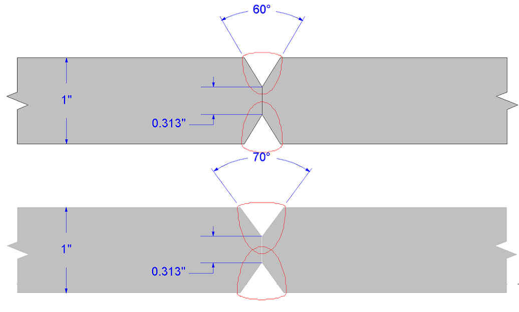
Figure 3. Two “Double-V” groove joint designs with different included angles. A larger angle can allow for improved penetration through the joint.
(Click on illustration to enlarge it)
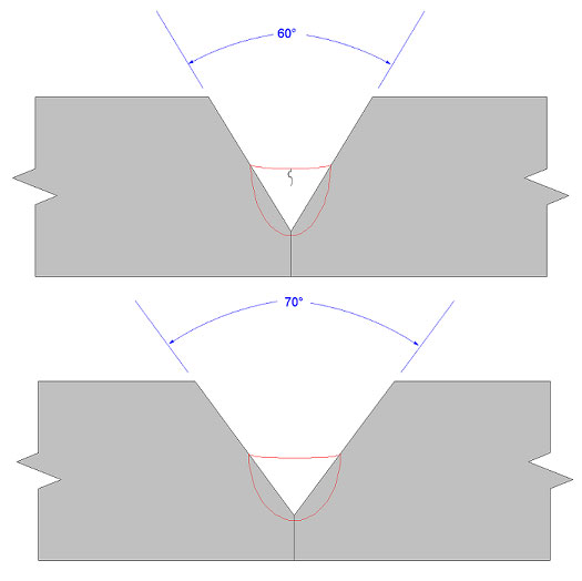
Figure 4. Illustration showing how a larger included angle can reduce crack sensitivity.
(Click on illustration to enlarge it)
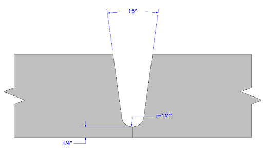
Figure 5. Example of a U-Groove weld joint configuration.
(Click on illustration to enlarge it)
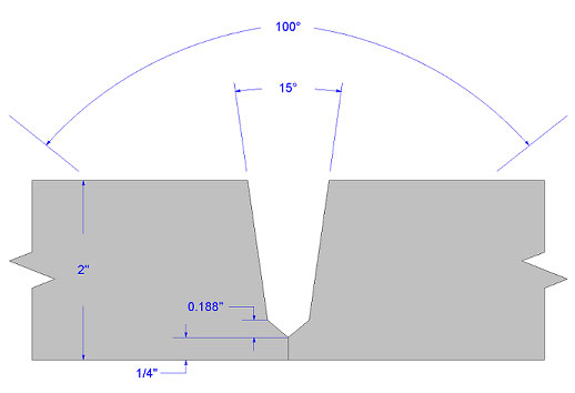
Figure 6. Example of a compound bevel groove weld joint.
(Click on illustration to enlarge it)
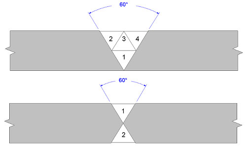
Figure 7. Comparison of Single-V and Double-V groove joint designs. A Double-V joint design utilizes about half of the weld metal of its Single-V counterpart.
(Click on illustration to enlarge it)
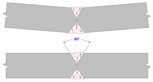
Figure 8. Comparison of two different pass sequence procedures. Less plate distortion can be achieved by balancing the weld passes.
(Click on illustration to enlarge it)
In the process of selecting a suitable butt weld joint preparation for thick plate (greater than 1 in), the most apparent consideration is unquestionably the joint economy – the practice of minimizing the volume of weld metal required to fill the joint. This desire to keep costs low is certainly understandable, as a fabricator would not want to deposit any more weld metal than is absolutely necessary so that profitability can be assured.
Yet as the thickness of the plates to be joined increases, the weld metal volume grows at an even faster rate due to the geometry of the weld joint, that is, the bevel angles. So which joint configurations provide the best economy? This will be outlined in more detail that follows. But before delving into this area, other important factors that must be considered when choosing the appropriate joint design must be discussed first.
One of those factors is the requirement that the weld joint needs to be able to physically accommodate the chosen welding process and any accompanying welding equipment (nozzles, torches, etc.). Consider the case where the joint design incorporates a bevel (on at least one side of the joint) and a root opening. Two examples of AWS D1.1 prequalified joint designs with this type of preparation are shown in Figures 1 and 2.
The B-U3c-S joint design shown in Figure 1 for submerged arc welds shows a 70 deg included angle, which is determined from the addition of the 35 deg bevel angle on both plates. Since the included angle of this joint is relatively large, then the root opening may be fit-up to be narrow without fear of the welding arc not being able to penetrate deep enough into the joint. In contrast, the B-U2-S joint design shown in Figure 2 displays a relatively small included angle of 20 deg. Because the bevel angle is small, the root opening must be increased far enough to allow for complete penetration through the joint.
Although the two joint configurations mentioned above are quite common, there are instances where it would benefit the fabricator to utilize a joint design that features a bevel and a root face (with no gap). The same logic regarding access to the weld joint that was used in the previous paragraph applies in this situation as well.
Because there is little (or no) gap, the bevel angle must be physically large enough to accommodate the welding process and welding equipment. But now there is the additional consideration as to whether or not the root face, also known as the “land”, is ideal when taking into account the depth of penetration of the selected welding process and parameters.
With a specified root face dimension, penetration level will be primarily dictated by the welding current and the travel speed. It is intuitive to see that as the welding current increases, the depth of penetration increases. Moreover, as the welding travel speed decreases, the penetration level increases with all other things being equal. So, if changes to the welding process and parameters are not possible (as is true in the case of qualified welding procedures), then it is even more important that great care be taken to properly size the root face dimension to ensure adequate penetration through the root, as illustrated in Figure 3.
This raises another vital concern in regards to the “bevel and root face” joint design. The joint preparation of the groove has a dramatic effect on the shape of the cross-sectional area of the first-pass weld nugget. It is imperative to achieve a weld that possesses a width-to-depth ratio of at least 1.25 in order to mitigate the crack-sensitivity of the weld. A width-to-depth ratio of 1.25 can be readily achieved when the included angle is at least 70 deg. The width-to-depth ratio associated with a joint that has an included angle of 60 deg or less can lead to surface or even sub-surface centerline cracks. Once the first pass has been deposited, however, the crack sensitivity associated with the included angle ceases to be an issue. This phenomenon is expressed in Figure 4.
In order to address the inherent crack sensitivity of V-groove type joints, some fabricators opt for the choice of a U-groove joint configuration as shown in Figure 5. The term “U-groove” stems from the application of a radius or partial circle preparation at the bottom of the joint. This radius transitions smoothly to a narrow included angle. Because of the large width-to-depth ratio provided by this U-groove configuration, a natural protection against cracking is provided. When employing a narrow bevel angle with a U-groove, the crack susceptibility is not amplified in the same way that it is with V-grooves.
Another type of narrow bevel joint configuration commonly referred to as a compound joint is shown in Figure 6. In the fabrication of a compound bevel joint, the included angle at the bottom of the joint is made to be large (say 100 deg). Moving up a short distance along the sidewall, the included angle makes an abrupt change to a much narrower included angle (to say 15 deg). Although these two types of narrow gap joint designs decrease crack sensitivity, they are not without drawbacks. One such drawback is that the plates must be machined during preparation rather than torch cut, which adds greatly to the cost of fabrication. However, this objection can be offset somewhat by the extra savings realized because smaller included angles can be used and therefore these joints require less weld metal than their V-groove counterparts.
As if that wasn’t enough to consider, the opportunity exists for the fabricator to make use of double-sided groove joints. The conventional wisdom is that because double-sided groove welds exhibit greater joint economy since the weld metal required is roughly 50 percent of that of their single-sided complements (see Figure 7), one may expect that double-sided joints are nearly 50 percent less expensive to construct.
Another perceived benefit to using double-sided joints is that because half the weld metal is required, then the chance for weld defects is also cut in half. And yet another logical assumption commonly associated with double-sided groove welds is that because fewer weld passes are used, there is a lower level of residual stresses present in the base material surrounding the weld. So considering these apparent benefits of double-sided groove welds, why would anyone want to use a single sided groove weld?
Although it is true that double-sided welds improve joint economy based simply on the geometry of the weld joint, it is not necessarily true, however, that they cut the cost of production in half. Because joint preparation now must be carried out from two sides of the plate rather than one, labor and cutting costs will double.
Another cost concern with double-sided groove welds is that two root passes must be deposited instead of one. As welding fabricators know, root passes are notoriously difficult to deposit – inadequate penetration, difficult slag removal, and sidewall undercut are just a few of the problems associated with the root pass. Furthermore, root passes generally take more time to deposit than the fill and cap passes, which counters the savings generated from the reduction in weld metal attributed to double-sided groove welds.
The same problems encountered in root pass welding of double sided groove welds also present themselves during overhead welding, which is obliged to be performed if the weldment cannot be re-positioned for downhand welding. And even if re-positioning of the weldment can transpire, it is not a one-time occurrence for each double-sided weld joint. On the contrary, the weld passes need to be deposited in a counter-balancing method similar to that shown in Figure 8 to achieve optimum distortion control.
While double-sided groove welds do offer improved joint economy over single-sided welds, the savings can be wiped out if the proper mechanization and positioning equipment is not used to reign in preparation and handling costs. And even if such equipment is utilized, the savings over single-sided welds may not necessarily be two-to-one. The same type of “pro-versus-con” arguments must be weighed out in order to make an informed decision when choosing between U-groove and V-groove joint preparations and small bevel versus large bevel configurations.
Subscribe to learn the latest in manufacturing.


