Fillet Welds Using Stainless Steel Shielded Metal Arc Electrodes
In developing this welding procedure, here’s how to look for the “keyhole” that is visible behind the arc and making sure that arc does not ride on top of the puddle.
Posted: May 9, 2012
The point is that if the same size fillet weld is deposited at the same travel speed with both a mild steel and stainless steel electrode, the stainless steel electrode will accomplish this at a lower amperage . . . significantly lower. And moreover, because stainless steel stick electrodes operate at a lower output current than mild steel electrodes, a lower arc force results. So by this logic, one can envision the problems that can arise by trying to push a lower output amperage through the same size weld puddle.
Undeterred, there are some who still believe that penetration through the root can be achieved simply by increasing the output amperage. But jacking up the current to the maximum recommended output amperage for a given electrode diameter (or beyond) will only result in a proportional increase in the melt-off rate. Also, the arc length – the distance from the end of the electrode to the workpiece – will increase. An increase in the arc voltage translates into a decrease in the current density, that is, the increased current is merely spread out over a larger area. So the net benefit to increasing the current is zero in regards to root penetration.
Alternatively, some have re-hashed the “I’ll just burn it in” comment by proceeding to decrease the travel speed. These folks justify their actions this by saying that when the welding heat input increases, the penetration automatically increases. But this simply is not the case – particularly with stainless steel electrodes. This is equivalent to pushing the same welding current through a larger weld puddle and expecting improved penetration into the root of the joint. So, as you can see, increasing the heat input can be a bad idea with stainless steel electrodes due to their lower current and arc force.
By not riding on the puddle – but rather staying ahead of it – another benefit is realized. Staying ahead of the puddle affords the welder the opportunity to dramatically shorten up the arc length (the welder must also be sure not to drag the coating of the electrode on the puddle or sidewall). And, the shorter the welder can keep this arc length distance, the greater is the output amperage! It seems counter-intuitive at first because the output current is “set” at the welding machine, but it is true. Even though the SMAW is considered to be a “constant current” welding process, the output varies depending upon the voltage.
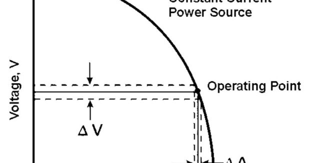
The amount by which the current increases depends upon the welding machine. For instance, a constant current machine that has a “vertical” output slope will respond with just a slight increase in current, even with a dramatic decrease in voltage as depicted in the simplified drawing in Figure 3.
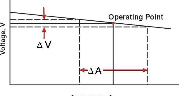
However, some constant current welding machines have a “drooper” output curve (which can be controlled with the “crisp” setting on some machines). When using these machines, a decrease in arc length and voltage can result in a significant increase in current as shown in the simplified output curve in Figure 4. This effect shown in this diagram is commonly referred to a machine that is providing a high “arc force.”
While this extra current will do little good if the arc is riding on the puddle, the boost in amperage can be highly beneficial if the arc is kept ahead of the puddle. By beneficial, I mean that a greater level of penetration can be achieved. Also, by keeping the arc length as short as possible, the arc energy is focused on a smaller area. This higher current density allows for a greater depth of penetration.
All of this theory is great, but there comes a point where the talking stops and the proving starts. So, the customer paid a visit to our facility, where we made several fillet welds on ½ in thick stainless steel plate in order to develop a welding procedure that would deliver consistent results. Using 5/32 in diameter Excalibur® E308/308L-17 electrode, we set the output current at 150 amps (the highest recommended for this diameter) in the constant current mode on a Flextec® 450 power source. We also set the crisp setting at its maximum in order to achieve the greatest amount of arc force.
By using proper technique, we were able to make welds that exhibited complete penetration through the root of the T-joint. The key to the proper technique was being sure that the arc was kept ahead of the slag that was continuously rolling to the bottom of the bead. We also maintained a very slight drag angle and kept the arc directed squarely at the root.
Ultimately, the largest weld bead size that could be attained in a single pass was between 3/16 in and ¼ in. Note that this is considerably smaller than the 5/16 in maximum fillet size that that I have mentioned previously for mild steel welds. But the take-home message is still the same – when using the SMAW process and a fillet weld larger than ¼ in for a stainless steel T-joint is required, be sure to do it with multiple passes.
At one point during the procedure development, the customer remarked at how fast I was traveling. As he mimicked my technique, he was able to get a feel for the speed and the mental focus that was required. In so doing, he learned to look for the “keyhole” that was visible behind the arc. Again, success in this application is only possible if the arc is not riding on top of the puddle.
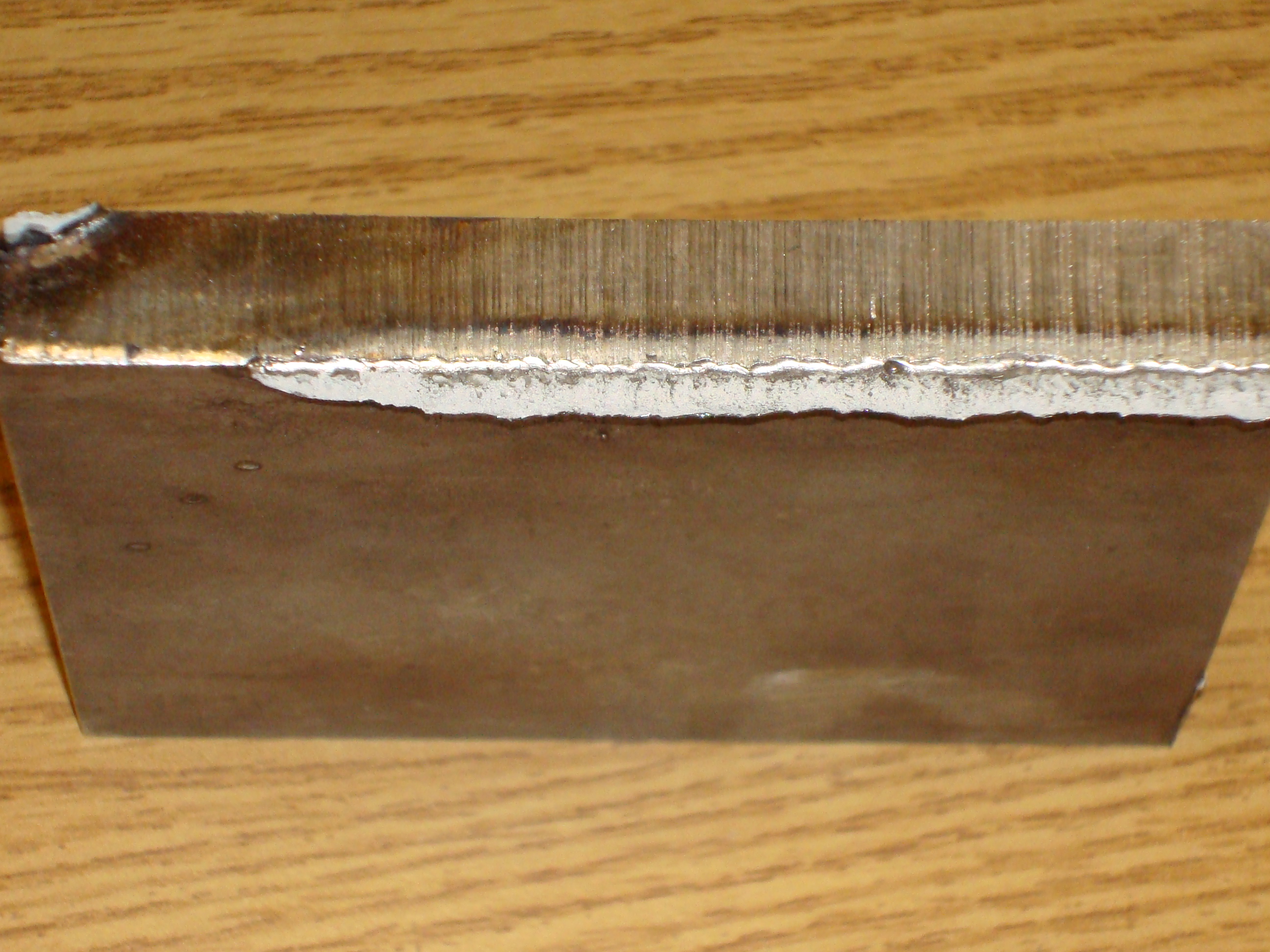
Upon breaking the welds via a fillet weld break test, the wavy edges of the “pores” on the underside of the weld indicated to us that full penetration through the root had been achieved. During a follow up discussion, I reiterated that the same principle – staying ahead of the puddle when welding in the downhand position – applies whether the SMAW process or other processes such as GMAW-P and FCAW-G are being used.


