Fillet Welds Using Stainless Steel Shielded Metal Arc Electrodes
In developing this welding procedure, here’s how to look for the “keyhole” that is visible behind the arc and making sure that arc does not ride on top of the puddle.
Posted: May 9, 2012
A little over a year ago, a customer asked me to assist with the development of shielded metal arc welding (SMAW) procedures for making horizontal fillet welds (2F position) in T-joints in stainless steel plate between varying from ½ in and 1 in thick. Their complaint centered around their inability to achieve penetration through the root of the T-joint consistently using stainless steel SMAW electrodes, even after accounting for plate preparation (oxides and/or surface contamination), welding current path (arc blow), welder ability, and all other factors that can be gleaned through process inspection.
Although a simple fix would have been to open up the root and place a small gap between the vertical and horizontal plate, this was not possible under the circumstances and the plates were fit-up “flush.” Regardless of the welding procedure used, he was simply not able to deposit the desired weld size while at the same time achieving full penetration. I’ll now offer my explanation as to why this was happening and discuss the successful outcome of my training session with the customer.
At this point, one might be wondering just how the customer was actually able to conclude that there was not full penetration. After all, it would be very difficult for the welder or inspector to simply “watch” the weld being deposited and declare that full penetration through the root had not been achieved. Furthermore, T-joints do not lend themselves very easily to have penetration evaluated by the standard non-destructive examination techniques because of their geometry. Those non-destructive examination techniques are MT (magnetic particle), PT (penetrant), UT (ultrasonic), and RT (radiographic or X-ray).
So did he determine depth of penetration by slicing practice T-joints transverse to the weld and generate a macro photograph? Perhaps, but this would only afford a snapshot of the weld profile at a specific point in time, and would only yield one data point regarding the depth of penetration along the entire length of the joint.
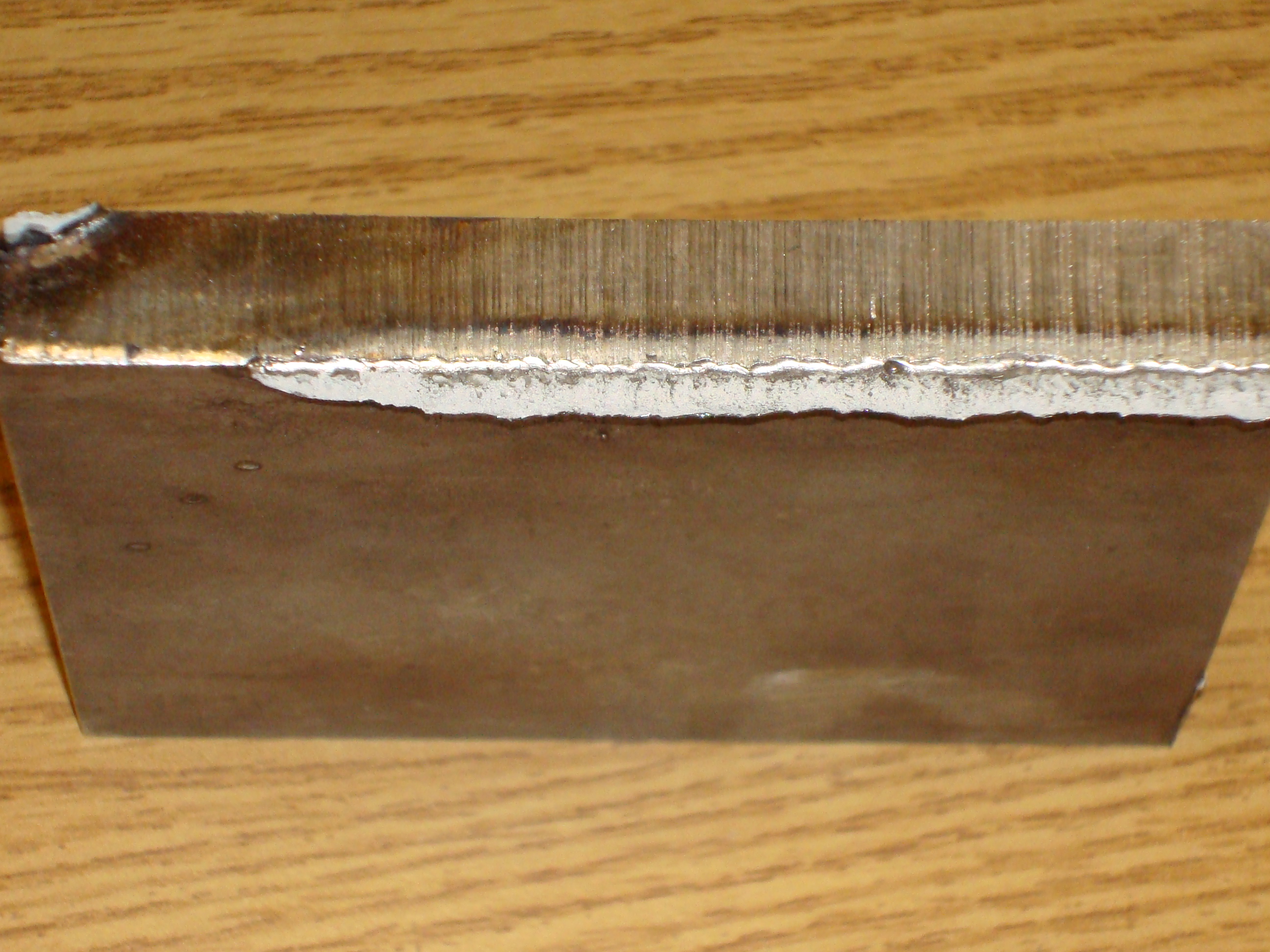
Ultimately, the customer was able to examine the extent of root penetration produced by their welding procedure by conducting a destructive examination called a fillet weld break test. In this test, the root of the weld is placed in tension for the purpose of exposing the underside of the weld for assessment. To visualize a fillet weld break test, imagine the vertical plate being folded over onto the horizontal plate in the manner shown in Figure 1.
The result of the customer’s analysis was that in all of the fillet welds he made using stainless steel stick electrodes, the original edge of the vertical plate was almost always completely intact. What the customer had hoped to see, however, was that there would be absolutely no sections of straightness on this edge and that it would appear to be wavy along the entire length. This exposed edge should resemble a “pore” as shown in Figure 2, indicating that the electric arc had made full penetration. Yet this is not the result that our customer was reporting.
Leading up to this point, the customer’s approach to solving this problem was to harken back on an old adage in the welding industry that is still often (and erroneously) used today: “If I need penetration, I’ll just burn it in.”
In other words, the welder will attempt to deposit a bigger weld bead in a single pass, believing that this technique will increase the level of penetration through the root of the joint. I’ve stated before in the context of welding with mild steel electrodes (“Focus on Proper Weld Size When Developing WPS Parameter Ranges,” Welding Tips, February 2011) that this approach can backfire, but it can be even more problematic when welding with stainless steel.
I’ve also been asked on several occasions, “Why can’t I expect to get better root penetration by depositing a larger, fatter weld?” The reason is that there is a maximum weld size that can be deposited in a single pass that will result in a weld that is free from lack of fusion, trapped slag, undercut at the toes, or the aforementioned lack of root penetration in T-joints.
Although the actual maximum fillet weld size depends upon the welding process – i.e., SMAW, FCAW, SAW, etc. – and the number of electrodes (as Tandem SAW is a possible process selection), the concept is still the same. The larger the weld bead, the greater the chance that the welding arc will be riding on the puddle. And the problems that I just mentioned are exacerbated when using stainless steel electrodes.
But what is the concern with stainless steel stick electrodes that warrants more caution? Look no further than the fundamental difference between mild steel and stainless steel. Stainless steel has a significantly higher melt-off rate at the same output current compared to mild steel. This higher melt-off rate is due primarily to the higher electrical resistivity of stainless steel compared to mild steel. In a nutshell, this means that the electric current encounters more internal resistance as it travels from the electrode holder (also known as the “stinger”) to the workpiece. This resistance causes the electrode to heat up more quickly and reach its melting point faster than mild steel electrodes.
So for the same amperage output setting on the welding machine, a considerably higher melt-off rate results when using stainless steel stick electrodes – upwards of 40 to 50 percent greater. Or stated another way, over nearly equivalent melt-off rate ranges, the operating window for 5/32 in Excalibur 7018 MR (a mild steel electrode) is 130 amps to 210 amps, while for 5/32 in Excalibur® 308/308L-17 (a stainless steel electrode) it is 95 amps to 150 amps.


