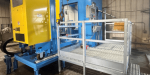
MACHINING CENTER BOOSTS CFRP FLOOR BEAM PRODUCTION BY 400 PERCENT
Hitco Carbon Composites manufactures CFRP aerospace structural parts and final machines them for direct delivery to “point of use” in the Boeing 787 program by using an advanced 5-axis profile beam milling machine from Bertsche Engineering.
Posted: May 7, 2011
Hitco Carbon Composites manufactures CFRP aerospace structural parts and final machines them for direct delivery to “point of use” in the Boeing 787 program by using this advanced 5-axis profile beam milling machine.
Hitco Carbon Composites, Inc. (Gardena, CA) was selected as one of the suppliers to Boeing 787 program for floor beams manufactured from carbon fiber reinforced plastic (CFRP). The company is one of hand full of manufacturers worldwide that has the capability of manufacturing complex (laid up) CFRP aerospace structural parts and final machining those parts for direct delivery to “point of use”.
Specific to the manufacture of floor beams, the process entails design and construction of detailed layup tools, using CNC controlled tape laying machines to form the structures that are then cured in large autoclaves. The cured floor beam profiles are sawed, edge routed, cut to length and drilled. They are manufactured as ship sets in a demand-driven on-off manufacturing environment, with each ship set corresponding to an aircraft order.
Floor beams in an airplane are those structural members that run crosswise down the length of the aircraft (see Figure 1). The length of the beam, which matches the width of the fuselage, varies as the fuselage widens going from front to center of the aircraft and then narrows again moving to the rear of the plane. While having a similar cross-section, each beam is manufactured to a different length and with a different hole drilling pattern that depends upon the location of the attaching connecting structural elements.
To keep floor beam weight to an absolute minimum, the design of each beam is further complicated by gauge (or in this case, layup thickness) reduction from end to center of the floor beam. The floor beam also has a recess section in the center third section that serves to route wiring and plumbing in the plane form fore to aft.
To address the complex manufacturing problems of machining trim and drilling these floor beams to the requisite tolerances at the required production rates, Hitco turned to Bertsche Engineering Corporation (Buffalo Grove, IL) to develop an advanced 5-axis profile beam milling machine for this purpose. Bertsche has a long history designing and building composite milling and drilling machines beginning with the 777 program, the first commercial airplane to use CFRP floor beams.
Over the course of several months the project requirements were fully defined. This schedule allowed Bertsche to incorporate many desired features into one fully automated machining system. The resulting full 5-axis P5 machine tool features automated part setup, part program control of all work holding fixtures, a wave milling feature and 100 percent part inspection.
The complex work holding fixtures can clamp beams of varying web width, varying flange length and programmable web thickness datum surfaces. The fixtures themselves are repositionable so that they can be prepositioned as part of an automated CNC setup program, as well as moved out the way during machining operations to provide better access to certain areas of the floor beam for cutting and drilling operations. The fixtures are individually controlled, but also operate as coordinated groups that open and close, lift and retract and reposition in synchronous fashion for part loading sequences, when machining ore when measuring parts.
The work holding fixtures are designed to hold U, H, J cross-sectional beams from 3.0 in width to 12.0 in width and can adjust for gauge reduction (web ply thinning for weight reduction). The fixtures automatically adjust to varying web and flange thickness. For added flexibility, the fixtures are removable from the supporting base. New or different style fixtures can be attached to the support, allowing the machine tool to be reconfigured for holding different style parts.
This machining system entered service in August of 2009 after subsequent qualification to the rigorous standard of the application. To enhance part positioning and flow, the system incorporates large vacuum tools that can be loaded into the machine tool and supported by the same flexible clamping-style work holding fixtures. Parts are now manufactured with either vacuum or mechanical clamping means as the process dictates.
Parts are machined dry. Dry machining is the preferred method of manufacture by aircraft manufacturers to avoid composite material swelling due to coolant absorption by material exposed from cutting. Coolants, especially oil base coolants, can interact with the composite material, causing the material to swell and the formation of residue that must then be cleaned after part machining. Dry machining also has an advantage because dust containment and removal is an easier problem to solve than preventing dust sludge buildup when the plastic material and cutting fluids forms a sludge that adheres to every crevice and nook in the system.
For dust containment all machining is done in a fully enclosed machining compartment with integral dust collection hoods that capture air borne dust, directing it out of the machine tool into a dust filtration system. Composite slugs, chards and similar material are swept into a debris collection chute with a debris pusher device as part of an automatic cleanup cycle. A set of large HEPA filters cleans the air to a safe level and a dust collection drum makes for easy machine cleanup and dust disposal.
The thermal coefficient of expansion of CFRP material is almost zero, while the machine tool expansion is primarily governed by the coefficient of expansion of steel. Due to the long length of the parts being manufactured, this difference becomes significant enough to adversely impact the hole location accuracy of features machined into the part. To insure manufacture of consistent length beams, thermal length compensation is used to adjust for length variation of the part based on the part and machine temperature.
To verify that parts are machined to tolerance and to meet the desire to measure the parts for dimensional accuracy in the same state in which they were machined, parts are 100 percent feature-inspected inside the machine. The inspection probe is used to verify the position of fixtures, datum surfaces of the fixture and dimensional inspection data for all drilled and milled features. The system is also equipped with a calibration sphere that allows the machine tool to quickly check itself for any position deviation and the inspection probe calibration software is used to insure 100 percent reliability of collected inspection data.
Now in full production, this machine tool drills, mills and saws complete floor beams on all sides in a single setup. The finish machined product is inspected using a full function metrology software package integral to the HMI front end PC. Parts are inspected for dimensional accuracy and statistical data is collected with complete tracking history created for each manufactured part.
The entire floor beam machining system is housed in a specially built facility that is temperature regulated. Engineering and manufacturing offices surround the machine tool, giving manufacturing engineers constant oversight of complete operations and allowing them to stay fully involved at all times with the manufacturing process. While current production rates are already four times faster than previous methods, continued program optimization and process improvements are being implemented by Hitco with the expectation that floor beam manufacturing times will be reduced by at least another 50 percent in the future.


